
Color Science and Technology in LCD and LED Displays

Key Terms
- Liquid Crystals Display (LCD)
- Light Emitting Diodes (LED)
- Organic LED (OLED)
- Active Matrix (AM)
- Active Matrix OLED (AMOLED)
- Quantum light-emitting diode (QLED)
- Quantum Dot LED
- Quantum dots nanorod LED (QNED)
- Mini LED
- Micro LED
- Color Filters (CFA)
- Backlighting
- Liquid Crystals
- Light Polarization
- Pixels
- Sub-Pixels
- RGB (Red Green Blue)
- White Light
- Blue LEDs
- Flat Panel Display
- CRT (Cathode Ray Tube)
- Phosphores
- Pigments
- Thin Film Transistors (TFT)
- Active Matrix TFT
- Twisted Nematic (TN)
- In Panel Switching displays (IPS Panels)
- Vertical Alignment Panels (VA Panels)
- Advanced Fringe Field Switching (AFFS)
- AM-LCD
- Plasma based Displays
- CCFL Fluorescent Lamps
- Flexible Displays
- FPD Flat Panel Display
- QD-OLED
- QD-LCD
- White LEDs
- RGB LED Lighting
- White LED Lighting
- QDEF Quantum Dot Enhanced Film
- LCM LC Module
- QD-CF QD Color Filter
- QD-LED based on Electroluminescence
- miniLED Backlit LCD
- Mini/Micro LED Emissive Displays
- Linear Polarizer in LCD
- Circular Polarizer in OLED
- Perovskite LEDs
- GB-R LED Green Blue LED + Red Phosphor
- RB – G LED Red Blue LED + Green Phosphor
- WCG-CCFL
- Color Resist
- Photo Mask
- Optical Film
- Neo QLED (mini LED)
- HDR and Rec.2020 compliant displays
- Adobe RGB Color Space
- Rec 709 Color Space
- DCI P3 Color Space
- Rec 2020 Color Space
- Color Gamut
- Contrast Ratio
- Brightness
- Luminescence
- High Dynamic Range HDR
- Color Volume
- Chromaticity
- 1pc-WLED Phosphor Converted White LED
- 2pc-WLED Phosphor Converted White LED
- Color Crosstalk
- Blue LED-pumped red and green QDs backlight
- Color Converted Film CCF
- Luminance
- GaN – Gallium Nitride
- lnGaN
- Colloidal Semiconductor QDs
- Semiconductor nanocrystal quantum-dot-integrated white- light-emitting diodes (QD-WLEDs)
- (Low Temperature PolySilicon LCD) LTPS LCD
- Poly-silicon (poly-Si)
- Amorphous silicon (a-Si)
- Organic–inorganic perovskite (OIP)
- Photo Resist
LCD (Liquid Crystal Display)
Definition
LCD (Liquid Crystal Display) is a type of flat panel display which uses liquid crystals in its primary form of operation. LEDs have a large and varying set of use cases for consumers and businesses, as they can be commonly found in smartphones, televisions, computer monitors and instrument panels.
LCDs were a big leap in terms of the technology they replaced, which include light-emitting diode (LED) and gas-plasma displays. LCDs allowed displays to be much thinner than cathode ray tube (CRT) technology. LCDs consume much less power than LED and gas-display displays because they work on the principle of blocking light rather than emitting it. Where an LED emits light, the liquid crystals in an LCD produces an image using a backlight.
As LCDs have replaced older display technologies, LCDs have begun being replaced by new display technologies such as OLEDs.
How LCDs work
A display is made up of millions of pixels. The quality of a display commonly refers to the number of pixels; for example, a 4K display is made up of 3840 x2160 or 4096×2160 pixels. A pixel is made up of three subpixels; a red, blue and green—commonly called RGB. When the subpixels in a pixel change color combinations, a different color can be produced. With all the pixels on a display working together, the display can make millions of different colors. When the pixels are rapidly switched on and off, a picture is created.
The way a pixel is controlled is different in each type of display; CRT, LED, LCD and newer types of displays all control pixels differently. In short, LCDs are lit by a backlight, and pixels are switched on and off electronically while using liquid crystals to rotate polarized light. A polarizing glass filter is placed in front and behind all the pixels, the front filter is placed at 90 degrees. In between both filters are the liquid crystals, which can be electronically switched on and off.
LCDs are made with either a passive matrix or an active matrix display grid. The active matrix LCD is also known as a thin film transistor (TFT) display. The passive matrix LCD has a grid of conductors with pixels located at each intersection in the grid. A current is sent across two conductors on the grid to control the light for any pixel. An active matrix has a transistor located at each pixel intersection, requiring less current to control the luminance of a pixel. For this reason, the current in an active matrix display can be switched on and off more frequently, improving the screen refresh time.
Some passive matrix LCD’s have dual scanning, meaning that they scan the grid twice with current in the same time that it took for one scan in the original technology. However, active matrix is still a superior technology out of the two.
Types of LCDs
Types of LCDs include:
- Twisted Nematic (TN)- which are inexpensive while having high response times. However, TN displays have low contrast ratios, viewing angles and color contrasts.
- In Panel Switching displays (IPS Panels)- which boast much better contrast ratios, viewing angles and color contrast when compared to TN LCDs.
- Vertical Alignment Panels (VA Panels)- which are seen as a medium quality between TN and IPS displays.
- Advanced Fringe Field Switching (AFFS)- which is a top performer compared IPS displays in color reproduction range.
LCD vs OLED vs QLED
LCDs are now being outpaced by other display technologies, but are not completely left in the past. Steadily, LCDs have been being replaced by OLEDs, or organic light-emitting diodes.
OLEDs use a single glass or plastic panels, compared to LCDs which use two. Because an OLED does not need a backlight like an LCD, OLED devices such as televisions are typically much thinner, and have much deeper blacks, as each pixel in an OLED display is individually lit. If the display is mostly black in an LCD screen, but only a small portion needs to be lit, the whole back panel is still lit, leading to light leakage on the front of the display. An OLED screen avoids this, along with having better contrast and viewing angles and less power consumption. With a plastic panel, an OLED display can be bent and folded over itself and still operate. This can be seen in smartphones, such as the controversial Galaxy Fold; or in the iPhone X, which will bend the bottom of the display over itself so the display’s ribbon cable can reach in towards the phone, eliminating the need for a bottom bezel.
However, OLED displays tend to be more expensive and can suffer from burn-in, as plasma-based displays do.
QLED stands for quantum light-emitting diode and quantum dot LED. QLED displays were developed by Samsung and can be found in newer televisions. QLEDs work most similarly to LCDs, and can still be considered as a type of LCD. QLEDs add a layer of quantum dot film to an LCD, which increases the color and brightness dramatically compared to other LCDs. The quantum dot film is made up of small crystal semi-conductor particles. The crystal semi-conductor particles can be controlled for their color output.
When deciding between a QLED and an OLED display, QLEDs have much more brightness and aren’t affected by burn-in. However, OLED displays still have a better contrast ratio and deeper blacks than QLEDs.
This was last updated in September 2019
Source: https://www.thoughtco.com/liquid-crystal-display-history-lcd-1992078
The History of Liquid Crystal Display
By Mary Bellis Updated March 02, 2019

An LCD or liquid crystal display is a type of flat panel display commonly used in digital devices, for example, digital clocks, appliance displays, and portable computers.
How an LCD Works
Liquid crystals are liquid chemicals whose molecules can be aligned precisely when subjected to electrical fields, much in the way metal shavings line up in the field of a magnet. When properly aligned, the liquid crystals allow light to pass through.
A simple monochrome LCD display has two sheets of polarizing material with a liquid crystal solution sandwiched between them. Electricity is applied to the solution and causes the crystals to align in patterns. Each crystal, therefore, is either opaque or transparent, forming the numbers or text that we can read.
History of Liquid Crystal Displays
In 1888, liquid crystals were first discovered in cholesterol extracted from carrots by Austrian botanist and chemist, Friedrich Reinitzer.
In 1962, RCA researcher Richard Williams generated stripe patterns in a thin layer of liquid crystal material by the application of a voltage. This effect is based on an electrohydrodynamic instability forming what is now called “Williams domains” inside the liquid crystal.
According to the IEEE, “Between 1964 and 1968, at the RCA David Sarnoff Research Center in Princeton, New Jersey, a team of engineers and scientists led by George Heilmeier with Louis Zanoni and Lucian Barton, devised a method for electronic control of light reflected from liquid crystals and demonstrated the first liquid crystal display. Their work launched a global industry that now produces millions of LCDs.”
Heilmeier’s liquid crystal displays used what he called DSM or dynamic scattering method, wherein an electrical charge is applied which rearranges the molecules so that they scatter light.
The DSM design worked poorly and proved to be too power hungry and was replaced by an improved version, which used the twisted nematic field effect of liquid crystals invented by James Fergason in 1969.
James Fergason
Inventor James Fergason holds some of the fundamental patents in liquid crystal displays filed in the early 1970s, including key US patent number 3,731,986 for “Display Devices Utilizing Liquid Crystal Light Modulation”
In 1972, the International Liquid Crystal Company (ILIXCO) owned by James Fergason produced the first modern LCD watch based on James Fergason’s patent.
Liquid Crystals in a Display
Source: Japan Display Inc.
LCD Basics
Liquid crystal
Liquid crystal refers to the intermediate status of a substance between solid (crystal) and liquid. When crystals with a high level of order in molecular sequence are melted, they generally turn liquid, which has fluidity but no such order at all. However, thin bar-shaped organic molecules, when they are melted, keep their order in a molecular direction although they lose it in molecular positions. In the state in which molecules are in a uniform direction, they also have refractive indices, dielectric constants and other physical characteristics similar to those of crystals, depending on their direction, even though they are liquid. This is why they are called liquid crystal. The diagram below shows the structure of 5CB (4-pentyl-4’-Cyanobiphenyl) as an example of liquid crystal molecules.
An example of a liquid crystal molecule

Principle of liquid crystal display
A liquid crystal display (LCD) has liquid crystal material sandwiched between two sheets of glass. Without any voltage applied between transparent electrodes, liquid crystal molecules are aligned in parallel with the glass surface. When voltage is applied, they change their direction and they turn vertical to the glass surface. They vary in optical characteristics, depending on their orientation. Therefore, the quantity of light transmission can be controlled by combining the motion of liquid crystal molecules and the direction of polarization of two polarizing plates attached to the both outer sides of the glass sheets. LCDs utilize these characteristics to display images.
Working principle of an LCD

TFT LCD
An LCD consists of many pixels. A pixel consists of three sub-pixels (Red/Green/Blue, RGB). In the case of Full-HD resolution, which is widely used for smartphones, there are more than six million (1,080 x 1,920 x 3 = 6,220,800) sub-pixels. To activate these millions of sub-pixels a TFT is required in each sub-pixel. TFT is an abbreviation for “Thin Film Transistor”. A TFT is a kind of semiconductor device. It serves as a control valve to provide an appropriate voltage onto liquid crystals for individual sub-pixels. A TFT LCD has a liquid crystal layer between a glass substrate formed with TFTs and transparent pixel electrodes and another glass substrate with a color filter (RGB) and transparent counter electrodes. In addition, polarizers are placed on the outer side of each glass substrate and a backlight source on the back side. A change in voltage applied to liquid crystals changes the transmittance of the panel including the two polarizing plates, and thus changes the quantity of light that passes from the backlight to the front surface of the display. This principle allows the TFT LCD to produce full-color images.
Structure of a TFT LCD

Source: https://madhavuniversity.edu.in/liquid-crystalline-materials.html

Source: Merck KGaA


Source: Merck KGaA
After over 120 years of research in liquid crystals, a large number of liquid crystal phases have been discovered. Liquid crystal phases have a range of different structures, but all have one thing in common: they flow in a similar way to viscous liquids, but show the physical behavior of crystals. Their appearance depends on various criteria, including molecular structure and temperature, as well as their concentration and the solvent.
A crystal can be described using a coordinate system. Each atom of a molecule has its specific position. The structure of a crystal can be reduced to a tiny unit, the primitive cell, which is repeated periodically in all three dimensions. This periodicity describes the long-range order of a crystal. A crystal is a highly ordered system in which the physical properties have different characteristics according to the viewing angle. This is called anisotropy. The properties of a liquid crystal phase are also anisotropic, although the structure can no longer be described in a coordinate system. The periodicity and thus the long-range order are lost. Molecules orient themselves by their neighboring molecules, so that only short-range order can be observed. In contrast, a liquid is a completely disordered system, in which the physical properties are isotropic, i.e. directionally independent. What a liquid crystal phase and a liquid have in common is fluidity.
THERMOTROPIC NEMATIC PHASE
In LCD technology, the thermotropic nematic phase is by far the most significant phase. It is formed from rod-shaped (calamitic) molecules that arrange themselves approximately parallel to each other. These molecules can also form smectic phases, which exist in multiple manifestations. Smectic phases are more ordered than nematic phases: as well as the parallel alignment of the molecules, they also form layers.
As the temperature rises, the order of a system decreases. The temperature at which a liquid crystal phase is converted to the isotropic liquid is called the clearing point. A substance may form one or more liquid crystal phases if the structural conditions allow this. However, the appearance of liquid crystal phases is not necessarily a consequence of the molecular structure.
Source: Liquid Crystalline materials used in LCD display
Source: https://madhavuniversity.edu.in/liquid-crystalline-materials.html

Types of LCD Technologies
Source: Merck KGaA
- Twisted nematic (TN)
- Vertical alignment (VA)
- Polymer stabilized VA variant (PS-VA)
- Self alignment vertical alignment (SA-VA)
- In-plane switching (IPS)
- Fringe field switching (FFS)
- Ultra-brightness fringe field switching (UB-FFS)
- Blue Phase
Source: Merck KGaA

Components of a LCD Panel
In Plane Switching IPS Technology
- Unpolarized Light
- Polarizer
- Glass Substrate
- Thin Film Transistor
- TFT Electrode
- Orientation Layer
- Liquid Crystals
- Polarized Light
- Orientation Layer
- Color Filter
- Glass Substrate
- Analyzer
- Emitted Light
Vertical Alignment VA Technology
- Back Lighting Unit (BLU) – Source of Unpolarized Light
- 1 st Polarizing Filter – Input Polarizer
- Glass Substrate – backbone
- Thin Film Transistor (TFT)
- TFT Electrode
- Orientation Layer – Thin Film Transistors
- RM/additive Polymer layer – orientation of liquid crystal molecules and for fixing “pretilt angle”
- RM Polymer Layer
- Liquid Crystals
- Polarized Light
- RM/additive polymer layer
- RM Polymer layer
- Orientation layer
- Electrode
- Color filter
- Glass Substrate
- 2 nd Polarizing filter
Materials used in making Displays
Source: Merck KGaA Germany
- Liquid Crystals
- OLED Materials
- Photoresists
- Siloxanes
- Silozanes
- LED Phosphores
- Quantum Materials
- Reactive Mesogens
Three main components of a LCD Panel are discussed below in some detail.
- Backplane Technology
- Color Filter
- Backlighting
Backplane Technology
What Is An LTPS LCD?
August 10, 2019
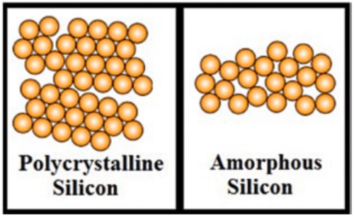
Low-temperature polycrystalline silicon (or LTPS) LCD—also called LTPS TFT LCD—is a new-generation technology product derived from polycrystalline silicon materials. Polycrystalline silicon is synthesised at relatively low temperatures (~650°C and lower) as compared to traditional methods (above 900°C).
Standard LCDs found in many consumer electronics, including cellphones, use amorphous silicon as the liquid for the display unit. Recent technology has replaced this with polycrystalline silicon, which has boosted the screen resolution and response time of devices.
Row/column driver electronics are integrated onto the glass substrate. The number of components in an LTPS LCD module can be reduced by 40 per cent, while the connection part can be reduced by 95 per cent. The LTPS display screen is better in terms of energy consumption and durability, too.
LTPS LCDs are increasingly becoming popular these days. These have a high potential for large-scale production of electronic devices such as flat-panel LCD displays or image sensors.
Amorphous silicon lacks crystal structure, whereas polycrystalline silicon consists of various crystallites or grains, each having an organised lattice (Fig. 1).
silicon (Credit: Wikipedia)
Advantages of an LTPS LCD display are:
- Dynamic and rich colours
- Fast response and less reflective
- High picture resolution
Some of its disadvantages are:
- Deteriorates faster than other LCDs
- High cost
Display technology explained: A-Si, LTPS, amorphous IGZO, and beyond

LCD or AMOLED, 1080p vs 2K? There are plenty of contentious topics when it comes to smartphone displays, which all have an impact on the day to day usage of our smartphones. However, one important topic which is often overlooked during analysis and discussion is the type of backplane technology used in the display.
Display makers often throw around terms like A-Si, IGZO, or LTPS. But what do these acronyms actually mean and what’s the impact of backplane technology on user experience? What about future developments?
For clarification, backplane technology describes the materials and assembly designs used for the thin film transistors which drive the main display. In other words, it is the backplane that contains an array of transistors which are responsible for turning the individual pixels on and off, acting therefore as a determining factor when it comes to display resolution, refresh rate, and power consumption. Note the transistors at the top of each colored pixel.
Examples of backplane technology include amorphous silicon (aSi), low-temperature polycrystalline silicon (LTPS) and indium gallium zinc oxide (IGZO), whilst LCD and OLED are examples of light emitting material types. Some of the different backplane technologies can be used with different display types, so IGZO can be used with either LCD or OLED displays, albeit that some backplanes are more suitable than others.
a-Si
Amorphous silicon has been the go-to material for backplane technology for many years, and comes in a variety of different manufacturing methods, to improve its energy efficiency, refresh speeds, and the display’s viewing angle. Today, a-Si displays make up somewhere between 20 and 25 percent of the smartphone display market.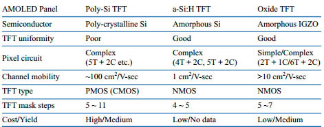 A spec comparison of common TFT types.
For mobile phone displays with a pixel density lower than 300 pixels per inch, this technology remains the preferable backplane of choice, mainly due to its low costs and relatively simple manufacturing process. However, when it comes to higher resolution displays and new technologies such as AMOLED, a-Si is beginning to struggle.
AMOLED puts more electrical stress on the transistors compared with LCD, and therefore favours technologies that can offer more current to each pixel. Also, AMOLED pixel transistors take up more space compared with LCDs, blocking more light emissions for AMOLED displays, making a-Si rather unsuitable. As a result, new technologies and manufacturing processes have been developed to meet the increasing demands made of display panels over recent years.
LTPS
LTPS currently sits as the high-bar of backplane manufacturing, and can be spotted behind most of the high end LCD and AMOLED displays found in today’s smartphones. It is based on a similar technology to a-Si, but a higher process temperature is used to manufacture LTPS, resulting in a material with improved electrical properties.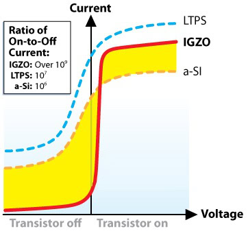 Higher currents are required for stable OLED panels, which a-Si falls short of.
LTPS is in fact the only technology that really works for AMOLED right now, due to the higher amount of current required by this type of display technology. LTPS also has higher electron mobility, which, as the name suggests, is an indication of how quickly/easily an electron can move through the transistor, with up to 100 times greater mobility than a-Si.
For starters, this allows for much faster switching display panels. The other big benefit of this high mobility is that the transistor size can be shrunk down, whilst still providing the necessary power for most displays. This reduced size can either be put towards energy efficiencies and reduced power consumption, or can be used to squeeze more transistors in side by side, allow for much greater resolution displays. Both of these aspects are becoming increasingly important as smartphones begin to move beyond 1080p, meaning that LTPS is likely to remain a key technology for the foreseeable future. LTPS is by far the most commonly used backplane technology, when you combine its use in LCD and AMOLED panels.
The drawback of LTPS TFT comes from its increasingly complicated manufacturing process and material costs, which makes the technology more expensive to produce, especially as resolutions continue to increase. As an example, a 1080p LCD based on this technology panel costs roughly 14 percent more than a-Si TFT LCD. However, LTPS’s enhanced qualities still mean that it remains the preferred technology for higher resolution displays.
IGZO
Currently, a-Si and LTPS LCD displays make up the largest combined percentage of the smartphone display market. However, IGZO is anticipated as the next technology of choice for mobile displays. Sharp originally began production of its IGZO-TFT LCD panels back in 2012, and has been employing its design in smartphones, tablets and TVs since then. The company has also recent shown off examples of non-rectangular shaped displays based on IGZO. Sharp isn’t the only player in this field — LG and Samsung are both interested in the technology as well.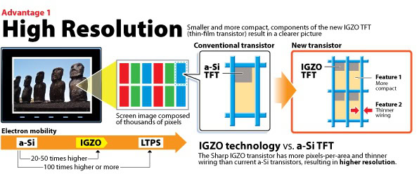 Smaller transistors allow for higher pixel densities
The area where IGZO, and other technologies, have often struggled is when it comes to implementations with OLED. ASi has proven rather unsuitable to drive OLED displays, with LTPS providing good performance, but at increasing expense as display size and pixel densities increase. The OLED industry is on the hunt for a technology which combines the low cost and scalability of a-Si with the high performance and stability of LTPS, which is where IGZO comes in.
Why should the industry make the switch over to IGZO? Well, the technology has quite a lot of potential, especially for mobile devices. IGZO’s build materials allow for a decent level of electron mobility, offering 20 to 50 times the electron mobility of amorphous silicon (a-Si), although this isn’t quite as high as LTPS, which leaves you with quite a few design possibilities. IGZO displays can therefore by shrunk down to smaller transistor sizes, resulting in lower power consumption, which provides the added benefit of making the IGZO layer less visible than other types. That means you can run the display at a lower brightness to achieve the same output, reducing power consumption in the process.
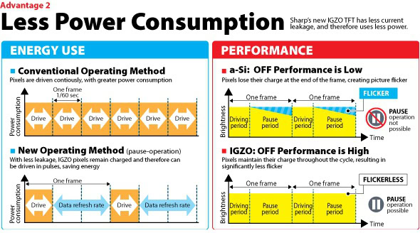
One of IGZO’s other benefits is that it is highly scalable, allowing for much higher resolution displays with greatly increased pixel densities. Sharp has already announced plans for panels with 600 pixels per inch. This can be accomplished more easily than with a-Si TFT types due to the smaller transistor size.
Higher electron mobility also lends itself to improved performance when it comes to refresh rate and switching pixels on and off. Sharp has developed a method of pausing pixels, allowing them to maintain their charge for longer periods of time, which again will improve battery life, as well as help create a constantly high quality image.
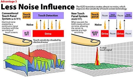
Smaller IGZO transistors are also touting superior noise isolation compared to a-Si, which should result in a smoother and more sensitive user experience when used with touchscreens. When it comes to IGZO OLED, the technology is well on the way, as Sharp has just unveiled its new 13.3-inch 8K OLED display at SID-2014.
Essentially, IGZO strives to reach the performance benefits of LTPS, whilst keeping fabrications costs as low as possible. LG and Sharp are both working on improving their manufacturing yields this year, with LG aiming for 70% with its new Gen 8 M2 fab. Combined with energy efficient display technologies like OLED, IGZO should be able to offer an excellent balance of cost, energy efficiency, and display quality for mobile devices.
What’s next?
Innovations in display backplanes aren’t stopping with IGZO, as companies are already investing in the next wave, aiming to further improve energy efficiency and display performance. Two examples worth keeping an eye are on are Amorphyx’ amorphous metal nonlinear resistor (AMNR) and CBRITE. Higher resolution smartphones, such as the LG G3, are putting increasing demands on the transistor technology behind the scenes.
Starting with AMNR, a spin-off project which came out of Oregon State University, this technology aims to replace the common thin-film transistors with a simplified two-terminal current tunnelling device, which essentially acts as a “dimmer switch”.
This developing technology can be manufacturing on a process that leverages a-Si TFT production equipment, which should keep costs down when it comes to switching production, whilst also offering a 40 percent lower cost of production compared with a-Si. AMNR is also touting better optical performance than a-Si and a complete lack of sensitivity to light, unlike IGZO. AMNR could end up offering a new cost effective option for mobile displays, while making improvements in power consumption too.
CBRITE, on the other hand, is working on its own metal oxide TFT, which has a material and process that delivers greater carrier mobility than IGZO. Electron mobility can happily reach 30cm²/V·sec, around the speed of IGZO, and has been demonstrated reaching 80cm²/V·sec, which is almost as high as LTPS. CBRITE also appears to lend itself nicely to the higher resolution and lower power consumption requirements of future mobile display technologies.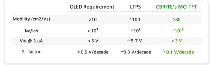 LTPS vs CBRITE spec comparison for use with OLED displays
Furthermore, this technology is manufactured from a five-mask process, which reduces costs even compared to a-Si and will certainly make it much cheaper to manufacture than the 9 to 12 mask LTSP process. CBITE is expected to start shipping products sometime in 2015 or 2016, although whether this will end up in mobile devices so soon is currently unknown.
Smartphones are already benefiting from improvements in screen technology, and some would argue that things are already as good as they need to be, but the display industry still has plenty to show us over the next few years.
Color Filter Array (CFA)
Source: BASF

Source: BASF
Cathode ray tube television sets have long had their day. Flat screen TVs now provide energy-efficient, low-emission entertainment in three out of four German households, according to the Federal Statistical Office. And this figure is rising, Germans are estimated to have purchased eight million flat screen television sets in 2015, most of which are LCDs. LCD technology is also the basis for many other contemporary communication devices, including smartphones, laptops and tablets. After all, with experts forecasting six percent global annual sales growth for flat-panel displays until 2020.
LCD stands for liquid crystal display. Liquid crystals form the basis for billions of flat-panel displays. The American, George H. Heilmeier, unveiled the first monochrome LCD monitor to the expert community in 1968. Commercialization of the first color monitors took another 20 years. Flat screen TVs started sweeping the world in the 1990s, mainly because of the availability of high-performance color filter materials.
The images on a liquid crystal display with the standard resolution are made up of about two million picture elements, better known as pixels. The color filter pigments attached to the liquid crystal cells are what give each pixel its color. Screen contrast and color purity remain a challenge, however.
Pigment properties make all the difference
Red, green, and blue: Every pixel contains these three primary colors. The colors are composed of tiny crystals about a thousand times smaller in diameter than a human hair. The crystals act as a filter for the white backlight and only allow light waves from a selected range of the visible spectrum to pass through. These light waves show one of the three colors in its purest possible form. The filters block all the other wavelengths. “A good pigment has a significant impact on the brilliance of the colors the viewer sees,” said Dr. Hans Reichert, head of colorants research at BASF.
“Although perfect color selection is not feasible with absorbing materials, we come fairly close to perfection with our red filters.” Color purity also has an impact on the range of colors available. The greater the purity of the three primary colors, the more permutations that can be achieved by mixing them – and the more colorful the image.
The picture shows a chemical reaction in the lab yielding diketopyrrolopyrroles, the substances BASF’s red filter pigments are made of. Diketopyrrolopyrroles are aromatic organic ring compounds mainly consisting of carbon, nitrogen and oxygen.
The basic principle is simple. When the color red appears on the screen, the corresponding subpixel lets the red portion of light pass through and absorbs the rest. The other two subpixels – for blue and green – are deactivated when this happens. If, on the other hand, light penetrates through the red and green subpixel while the blue is deactivated, the colors combine to give a rich yellow. Fine-tuning the portions of the three primary colors in this manner produces millions of hues.
The liquid crystals fine-tune the blend of colors by twisting the plane of oscillation of the light waves. “This determines the brightness and color of the subpixels,” said Ger de Keyzer, in charge of applications engineering for color filter materials at BASF. “The liquid crystals change direction, and in that way alter their optical properties depending on the voltage applied.” They rotate the plane of oscillation of light waves to allow the light to pass through the second polarization filter. When an electrical field is applied, however, the crystals prevent some or all of the light from getting through.
To ensure that subpixels switch on and off the way they are supposed to, it is essential to prevent interferences from the color filter pigments. Any interferences resulting in scattering and depolarization of light will allow the light to pass uncontrolled through the filter. This contaminates the colors and compromises the contrast.


Smaller the better
“A good rule of thumb is: The smaller and more regular the crystals, the lower the scattering and the better the LCD image quality,” de Keyzer said. Researchers control the process mainly by managing the conditions in which pigment crystallization takes place. The underlying molecular structure is what determines which parts of the color spectrum are filtered out.
The organic red pigments that BASF manufactures consist mainly of carbon, nitrogen, and oxygen, and belong to the class of diketopyrrolopyrroles (DPPs). Blue and green pigments are phthalocyanine metal complex compounds. The raw product produced through chemical synthesis is mainly composed of irregular particles. They must then be brought into the ideal size and shape. This is done by a process called pigment finishing. Crystals that are too small are dissolved and precipitated onto the larger crystals. Crystals that are too large are broken into smaller pieces by a mechanical process until the balance is right. Dr. Roman Lenz, BASF lab team leader in charge of new color filter material synthesis, explained: “Our technology gives us color particles of 20 to 40 nanometers – small enough to reduce light scattering to an absolute minimum but large enough to provide a high degree of stability.” BASF has honed the technology almost to perfection with its products. The color particles in the latest generation of the Irgaphor® Red product suite are smaller than 0.00004 millimeters, and have double the contrast performance of their predecessors.
Tomorrow’s television screens will have to meet even higher expectations in terms of resolution and color purity. In anticipation of the new demands, Lenz and his colleagues are taking their lab experiments one step further. Their aim is to find new materials that will show colors in an even more natural light.
Source: STRUCTURE OF COLOR FILTERS/Toppan

Market Demands for Color Filters
Source: Toppan Japan


Source: STRUCTURE OF COLOR FILTERS/Toppan


Manufacturing Process of Color Filters
Source: Toppan Japan

Dyes and Pigments Used in Color Filters
- Red Pigment/Dye
- Green Pigment/Dye
- Blue Pigment/Dye
High Transmittance, Low Scattering
Source: Past, present, and future of WCG technology in display

Dyes/Pigment Suppliers
- DIC/Sun Chemicals. – Green and Blue
- BASF – Red
- Merck KGaA
- Solvay
- Clariant
- Sumitomo Chemicals
Source: DIC Japan
Pigments for Color Filters Used in LCDs and OLED Displays(Functional Pigments)
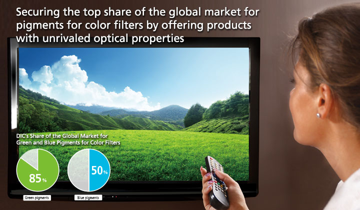
Value Creation Global market-leading pigments that deliver outstanding brightness and picture quality
Color images on liquid crystal displays (LCDs) used in LCD televisions, computers and smartphones are produced using the three primary colors of light—red (R), green (G) and blue (B). These colors are created using pigments. LCDs produce images by transmitting light emitted from a backlight lamp through a color filter to which an RGB pattern has been applied. As a consequence, the pigments used in the color filter are crucial to picture quality.
With Japan’s shift to digital terrestrial television driving up demand for flatpanel LCD televisions and the popularity of smartphones increasing, in 2007 DIC launched the G58 series of green pigments, which achieved a remarkable increase in brightness. The series includes FASTOGEN GREEN A350, a green pigment characterized by outstanding brightness and contrast that ensures excellent picture quality even with little light from the backlight. In fiscal year 2014, DIC developed the G59 series of green pigments for wide color gamut color filters, which deliver superior brightness and color reproduction, making them suitable for use in filters for next-generation high-definition displays, including those for ultra-high-definition (UHD) televisions. DIC currently enjoys an 85%- plus share of the global market for green pigments for color filters, making its products the de facto standard. DIC also manufactures blue pigments for color filters. In 2012, the Company developed the A series, which boasts a superb balance between brightness and contrast. The optical properties of pigments in this series have earned high marks from smartphone manufacturers and boosted DIC’s share of the global market for blue pigments to approximately 50%.
DIC’s pigments for color filters, which satisfy the diverse performance requirements of displays used in LCD televisions, smartphones, tablets and notebook computers while at the same time adding value, have been adopted for use by many color filter manufacturers. In addition to improving picture quality, these pigments reduce energy consumption and, by extension, lower emissions of CO2. Having positioned pigments for color filters as a business that it expects to drive growth, DIC continues working to reinforce its development and product supply capabilities.
Applying technologies amassed through the production of printing inks to the development and expansion of functional pigments that have become the de facto standard worldwide
DIC first succeeded in developing offset printing inks in-house in 1915 and 10 years later began production of organic pigments for its own use. Over subsequent years, the Company amassed development and design capabilities, as well as production technologies, crucial to the manufacture of fine chemicals and in 1973 commercialized revolutionary high-performance, long-lasting nematic LCs, which were adopted by Sharp Corporation for use in the world’s first pocket calculator incorporating an LCD. DIC’s passion and development prowess are also evident in its pigments for color filters.
Large-screen LCD televisions are expected to deliver superbly realistic and accurate color reproduction. The small LCDs used in smartphones and other devices must be clear, easy to read and bright enough to ensure legibility even with less light. This is because reduced light requirements results in longer battery life. Increasing brightness requires making color filters thinner and more transparent, but this alone will not deliver vivid colors and resolution. With the question of how best to realize both high brightness and vivid colors on ongoing challenge for display manufacturers, DIC has responded by developing innovative pigments for this application.
Copper has traditionally been the central material used in green pigments. In developing its green pigments for color filters, DIC defied conventional wisdom by exploring the use of a different central material with the goal of further enhancing performance characteristics. Through a process of trial and error, the Company narrowed down the list of suitable materials from a wide range of candidates, eventually choosing zinc. DIC also significantly improved transparency by reducing the size of pigment particles, thereby achieving a dramatic increase in contrast, which ensures a bright, clear picture quality even with less light. The outcome of these efforts was the groundbreaking G58 series.


Picture quality is influenced significantly by the brightness and contrast of the pigment used in the color filter. (Left: High brightness and high contrast; Right: Low brightness and low contrast)
In the area of blue pigments for color filters, DIC also leveraged its superior molecular design capabilities to achieve outstanding tinting strength and precise particle size control. To develop the A series of blue pigments for color filters, the Company also employed specialty particle surface processing to ensure highly stable dispersion, realizing an excellent balance between brightness and contrast. Products in the A series currently dominate the market for blue pigments for color filters, delivering excellent optical properties that continue to earn solid marks from smartphone manufacturers.
DIC’s success in developing a steady stream of pioneering functional pigments is supported by the seamless integration of basic technologies amassed in various fields as a manufacturer of color materials, the crossbusiness R&D configuration of its Central Research Laboratories and production technologies that facilitate the mass production of products with performance characteristics realized in the laboratory.
KEY PERSON of DIC
We are making full use of the DIC Group’s global network at all stages, from the promotion of product strategies through to the expansion of sales channels.

The value chain extending from functional pigments through to color filters for LCDs encompasses manufacturers of pigments, pigment dispersions, resist inks, color filters and LCDs. In developing pigments for color filters, we gather information on the latest trends from LCD manufacturers, which we apply to the formulation of nextgeneration product strategies.
Production of pigment dispersions, color filters and LCDs is concentrated primarily in East Asia. Recent years have seen a particularly sharp increase in the People’s Republic of China (PRC), which is on the verge of overtaking the Republic of Korea (ROK) as No. 1 in terms of volume produced. We are making full use of the DIC Group’s global network by working closely with local Group companies to bolster the adoption of DIC pigments for color filters for use in LCDs.
Manager, Pigments Sales Department 2, Pigments Product Division Naoto Akiyama
Source: Emperor Chemicals China
Color filter (CF, COLOR FILTER) is one of the most important components of a color liquid crystal display, which directly determines the quality of the color image of the display. The rapid growth of LCD displays is supported by the strong demand for flat-panel color displays from notebooks (PCs, Personal Computers). The portable characteristics of the LCD, such as small outline size, thinness, lightness, high definition, and low power consumption, greatly meet the needs of notebook PCs. It is believed that in the multimedia age, TFT-LCD will have a huge advantage. Color filters are the key elements that make up a color image.
The color of the color filter may be dyed with a water-soluble dye, or a pigment dispersion method in which a pigment is colored. The pigment dispersion method includes the use of UV-curable phtoresists: colored pigments, UV-curable carrier resins, photo initiators, organic solvents, dispersants and other ingredients, among which organic pigments are colored The requirements for coloring properties of the agent, such as high vividness, specific primary color (RGB), three spectral hue, durability, chemical resistance and high transparency, etc., are mainly the selection of high-grade organic pigments through efficient dispersion Treatment process to obtain a pigment dispersion with a fine and stable particle size, and to prepare photoresist inks for color filters. Compared with the dyeing method, it has excellent moisture resistance, light fastness, and heat stability, but the pigment dispersion must be further improved Technology to prepare color filters with high transparency and pigment purity.
The color filter in the liquid crystal display adopts the principle of additive method, and uses blue, green and red organic pigments. Based on the spectral color and durability requirements of colorants, pigments for blue and green color photoresist inks are usually selected: phthalocyanine CI pigment blue 15: 1, pigment blue 15 :0, pigment blue 15: 3, Pigment Blue 15: 4, Pigment Blue 15: 6, and anthraquinone-based pigments such as CI Pigment Blue 60 and the like. Green tone C.I. Pigment Green 36.
In particular, the spectral absorption characteristics of CI Pigment Blue 15: 6 and CI Pigment Green 36 are well matched with the wavelengths and emission intensities of the blue, green, and red fluorescence emission spectra (fluorescence lamp for LCD backlight) in liquid crystal displays. In order to further improve the spectral characteristics, it is possible to adjust by adding a small amount of pigments of other colors, such as adding CI Pigment Violet 23 to obtain a stronger red light blue, and adding CI Pigment Yellow 150 to obtain a stronger yellow light green.
The selection of pigments should be based on obtaining a high-definition spectrum, eliminating unnecessary wavelength spectra, and retaining only the necessary color light. Selecting the organic pigment varieties required by the appendix, the color light purity and transmittance of the color filter can also be improved.
In order to adjust the spectral characteristics of the color filter, such as hue, tinting strength and contrast, for red, green and blue spectrum pigments, a second pigment component is often added to fight the color. For example, select some yellow with excellent durability, Purple organic pigment varieties, CI Pigment Yellow 138, CI Pigment Yellow 139, CI Pigment Yellow 150, CI Pigment Yellow 180, CI Pigment Purple 23 and other varieties.
Recommended organic pigments of three primary colors of red, blue and green are as follows:
Red organic pigments: The main varieties are high-grade organic pigments such as: C.I. Pigment Red 122, C.I. Pigment Red 177, C.I. Pigment Red 242, C.I. Pigment Red 254, and specific yellow organic pigment varieties are added if necessary.
Green organic pigments: C.I. Pigment Green 7, C.I. Pigment Green 36 is mainly selected, and specific yellow organic pigment varieties are matched, and specific yellow organic pigment varieties are added if necessary.
Blue organic pigments: C.I.Pigment Blue 5, C.I.Pigment Blue 15: 3, C.I.Pigment Blue 15: 6, C.I.Pigment Blue 60, etc., if necessary, specific yellow pigments and pigment violet 23.
Color Filter Less Technology
The liquid crystal display (LCD)is a thin, flat display device, which is made up of many number of color or monochrome pixels arrayed in front of a light source or reflector. It is prized for its superb image quality, such as low-voltage power source, low manufacturing cost, compared with other display device including CRT, plasma, projection, etc. Today the LCD device has been widely used in portable electronics such as cell phones, personal computers, medium and also in large size television display.
The LCD device consists of two major components, TFT-LCD panel and Back Light Unit (BLU). As LCD device can not light actively itself, thus a form of illumination, back light unit is needed for its display. While one of the key parts in LCD panel is color filter. The color filter is a film frame consists of RGB primary colors, and its function is to generate three basic colors from the back light source for LCD display. As a whole, back light and color filter are the two vital components of the perfect color display for LCD device.
Traditionally people use the cold cathode fluorescent lamp (CCFL)as the back light source for medium and large size LCD device. However CCFL has several disadvantages. For example, narrow color representation, low efficiency, complex structure, limited life, and the CCFL needs to be driven by a high-voltage inverter, consequently requires more space. Another disadvantage is the environmental problem for the mercury inside it. So people try to find an ideal back light module for LCD display.
Nowadays, the back light technology for LCD device towards the trend of using light emitting devices (LED). For its excellent advantages, the LCD device based on LED back light owns promoted display performance. As a new generation of solid-state light source, LED can produce very narrow spectrum, thus can generate a high color saturation, as a result it provides LCD device delivering a wider color gamut of above 100% of NTSC specification than the only 70% of CCFL back light. Moreover the LED only need DC power drive instead of a DC-AC inverter, so simplifies the back light structure. In a word, LED back light makes LCD obtain quite a higher display quality than the conventional CCFL back light. Despite of these advantages, there are also several challenges for LED back light technology currently, such as efficiency, stable ability, heat dissipation and cost etc. so people are trying to get some substantial breakthrough at the technical problems above to make LED back light as the key technology part for LCD device.
Color filter is another key component of the LCD device. As a sophisticated part, its fabrication takes an extremely complicated process, consequently the color filter occupies quite a large proportion of the production cost of the LCD devices. While a serious deficiency is its greatly influence on the light utilization rate. Generally speaking, only about 30% the amount of the light emitted from the back light can be delivered, while the rest of the light is wasted while passing the color filter.
For this, people prefer to designing a new form of LCD module which can get rid of the color filter, to promote the efficiency of light utilization. So an idea of Color Filter-Less (CFL) technology was put forward. The Field Sequential color LCD designed by Sumsang company is the first form of Color Filter-Less technology which is an idea of changing the space color mixing into the time color mixing.
Especially, we design a film frame which is patterned of red and green emitting phosphors, then make it be excited by blue light from a blue LED panel we fabricated. For its special emitting mechanism, this phosphor film can generate red and green emissions respectively. Meanwhile not all the blue light is absorbed by the phosphors, the remnant blue light can pass the film frame, therefore we can achieve a panel frame on which the RGB colors mixed together, thus to replace of the color filter in LCD device.
Backlighting
- CCFL Cold Cathode Fluorescent Lamp
- LED
- RGB LED Backlighting
- An Edge backlight with white LEDs
- A flat backlight based on white LEDs
Source: TFTCentral.co.UK

Recent Technological Innovations
- LCD with LED Backlighting
- Mini LED
- Micro LED
- LCD with Quantum Dot QDEF
- Wide Color Gamut WCG
- Color Filter Less LCD
- Vertically Stacked OLED Layers (SOLED)
- Quantum Dot Color Filter QDCF
- RGBW LED 4 colors
- Bright Dyes and Pigments
- Color Filters using Structural Colors
- Transreflective Displays
- Reflective Displays
- Blue LED plus Red Green Color Filter
- Flexible displays -bendable, rollable, fixed, curved, foldable
- Touch Screens
- Transparent Displays
Vertically Stacked RGB OLED layers (SOLED)
Source: Three-terminal RGB full-color OLED pixels for ultrahigh density displays
https://www.nature.com/articles/s41598-018-27976-z


TFT based Vertically stacked OLEDs
Source: Thin-film transistor-driven vertically stacked full-color organic light-emitting diodes for high-resolution active-matrix displays
https://www.ncbi.nlm.nih.gov/pmc/articles/PMC7264127/

Supply Chain for TFT-LCD Manufacturing

Light Emitting Diodes (LEDs)
What are the different types of RGB LEDs?
The following are the different types of RGB LEDs:
- R/G/B/W – Has an additional white LED. This is often used where you need a pure white as well other combined colors.
- RGB / 3 in 1 LED – Uses a red, a blue and a green LED chip are mounted within a common light engine and focused through a lens to produce a more uniform hue across the beam of light.
- RGBW / 4 in 1 LED – similar to the RGB LED but with a warm white LED integrated in the light engine to offer more color tones.
- RGBA – Has an additional amber LED chip.
White vs RGB LEDs
White LED’s are actually blue leds with a yellow phosphor, and thus creating an white impression. This technique allows a colour gamut slightly wider than sRGB, but not very “colourfull”. RGB leds consist of 3 individual colour leds, red, green and blue. These allow an enourmous colour gamut that covers most standards like AdobeRGB and NTSC. Panels with RGB LED’s are much more expensive, as they need much more calibration logic. It is very hard to tame extreme gamut for say sRGB use, and the ballance of the colours is constantly monitored. RGB LED displays are doing twice the price of WLED’s with ease.
Composition of OLED Display
- RGB OLED
- White OLED
Source: Past, present, and future of WCG technology in display

OLED Technologies
- Shadow Mask Patterning Method
- Color Filter Method
Source: https://global.pioneer/en/corp/group/tohokupioneer/mainbusinesses/oled/introduction/

Color Patterning Technologies
Ink Jet and Photolithography are methods of making color filters.
Source: https://onlinelibrary.wiley.com/doi/10.1002/9781119187493.ch5
This chapter discusses the color patterning technologies, which gives major contribution to cost and productivity. The technologies discussed include shadow mask patterning, white‐color filter method, laser‐induced thermal imaging method, radiation‐induced sublimation transfer method, and dual‐plate OLED display method. Low material utilization can bring high cost, so it is very critical to suppress material consumption during OLED display manufacturing. To address this, various high‐material‐utilization next‐generation OLED manufacturing processes, such as the vapor injection source technology (VIST) method, hot‐wall method, and organic vapor‐phase deposition (OVPD) have been proposed and are discussed in the chapter.
OLED Production: Composition and Color Patterning Techniques
Last updated on January 22, 2020
Organic Light-Emitting Diodes (OLEDs) are most famously known for their use in foldable smart phone displays. From the Samsung Galaxy Fold to the Huawei Mate X (2019), these devices offer huge screens that can fold down to the size of a more traditional smartphone screen. This revolutionary new technology is made possible by the properties and composition of OLED screens. In traditional Liquid Crystal Display (LCD) screens, a glass pane covers the actual liquid crystal display that emits the light. On the other hand, OLED screens have the light emitting technology already built into them. Thus, when you touch interact with an OLED device, you are touching the actual display too. OLED screens are often made of a type of plastic, which allows for flexibility and folding screens. These devices also require OLED color patterning techniques in order to integrate color into the display devices, which we will describe further in the upcoming sections.
Intro to OLED Composition
Now, we will brief on the composition and integration of OLED technology in this plastic screen. OLEDs are made of two or three organic layers sandwiched between two electrodes (cathode and anode) on top of a substrate layer. The organic layers and electrodes emit light in response to an electric current. One of the most difficult processes in manufacturing these OLEDs is attaching the organic layers to the substrate. For example, organic vapor phase deposition and inkjet printing are both efficient methods that can reduce the cost of producing OLED displays.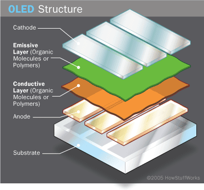
OLED components include organic layers that are made of organic molecules or polymers. This diagram is a two (organic) layer model.
Courtesy of HowStuffWorks.
Another big part of OLED manufacturing is the color patterning step, which allows the OLED device to display color. There are various methods in use for OLED color patterning, including photolithography. Lithography is commonly used for semiconductors and TFTs, but presents challenges for OLEDs. This is due to the high temperature and humid conditions required for attaching OLED layers together. In this article we will explore three different color patterning technologies that have arisen for more efficient and accurate OLED optical manufacturing.
OLED Color Patterning and Masking Techniques
First, we have the “Shadow Mask Patterning Method” consists of placing red, green, and blue light emitting layers in a pattern in each pixel of the OLED device. Further, this has the advantage that each subpixel gets appointed a single, distinct color which produces great clarity of images. Unlike the other methods, there are no outer color filters required to produce the images. Thus, this method saves energy and is one of the most efficient. However, utilizing shadow masks can be an error filled process because the RBG subpixel pattern is outlined with a physical mask a.k.a stencil. We show an example of an accuracy error and its effects in the images below.![]()
Error produced in processing an OLED with a red pixel mask. We can see that the spacing in the pattern is off around the red arrow. Courtesy of Tsujimura.![]()
The resulting color variation in OLED screen due to shadow mask deformation. shown above. Courtesy of Tsujimura.
Second, we have the “Color Filter Method” a.k.a. “White+Color Filter Patterning” method. In this method, the OLED itself is also designed and manufactured with all three color elements in each pixel. However, different from the “Shadow Mask Patterning” method, these OLEDs only produce white light. Next, additional red, green, and blue color filters are utilized to match the desired color output. Accordingly, this process allows for a dynamic range of colors to be emitted with different levels of filtering. However, a big consequence of using color filters is that the purity of the image may be compromised due to interactions of the OLED light and physical color filters. Equally important is the high power consumption this method eats up. Because the color filters absorb most of the light intensity, the process requires a constant, powerful back light.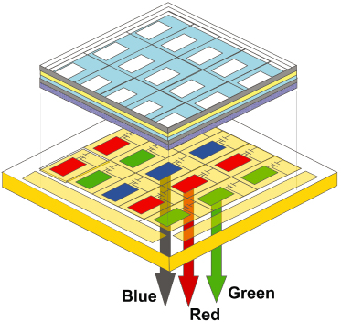
Schematic diagram of White+Color filter patterning method for OLEDs. Courtesy of Tsujimura.
Rising OLED Color Patterning Techniques: Electron Beams
In 2016, a new approach for OLED color patterning was developed at the Fraunhofer Institute for Organic Electronics. Researchers utilized electron beam technology to color pattern the organic layers in the OLED. Because this process acted on the micro-scale, it produced extremely accurate, high-resolution results, even with the help of color filters. Further, it also allowed for complex patterns and high-definition (HD) grayscale images. Since then, this technology has been developed and advanced to that of full-color working OLED displays, without the use of external filters.
Now, we will discuss an overview about how the electron beam process works. First, an OLED is produced containing all three RGB organic emitting layers. Akin to the previously mentioned processes, this OLED is designed to produce only white light. Next, a thermal electron beam is directed on the white emitting OLED. The electron beam excites certain molecules in the organic layer of the OLED, which causes the molecules or atoms to separate and become structured. Consequently, the thickness of different areas in the OLED organic layer changes and pixels with distinct colors (RGB) are formed. Moreover, the electron beam patterning process allows for microstructuring into color pixels without perturbing the other substrate and electrode layers.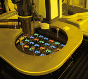
Probe station with patterned OLEDs in the clean room.
Courtesy of Fraunhofer FEP.
Conclusion
As more AMOLED, and flexible displays enter the market, OLED technology will continue to become more popular and widespread. One of the most important considerations for OLED availability in mass market, is in screen color production. Rising techniques such as the Electron Beam Patterning method can produce high quality, low cost, and energy efficiency. Another key consideration in OLED screen production is low material consumption. Further rising techniques in research that allow for low material costs include the vapor injection source technology (VIST) method, hot‐wall method, and organic vapor‐phase deposition (OVPD) [1].
This article is made possible by Gentec-EO, the market leader in the manufacture of light detection devices.
Further Reading
[1] https://onlinelibrary.wiley.com/doi/10.1002/9781119187493.ch5
Supply Chains of OLED Displays
Cover Glass
- Corning Glass
- Samsung Corning Advanced Glass
TFT Backplane
- Samsung UBE Materials
- Sumitomo Chemicals
Frontplane
- Universal Display Corporation UDC USA
Encapsulation
- Samsung SDI for Flex OLED
- KYORITSU CHEMICAL Japan
IC Driver
- Samsung Semiconductors
- Synaptics USA
Global Supply Chains for OLED Displays
Silica Sand
- Sibelico (Belgium)
- US Silica (US)
- Emerge Energy (US)
- Badger Mining (US)
- Wuxi Quechen Silicon Chemical Co. (China)
Display Glass
- Corning (US)
- Asahi Glass (Japan)
- Nippon Electric Glass (Japan)
IC Driver
- Samsung (South Korea)
- Novatek (Taiwan)
- Himax (Taiwan)
- Silicon Works (South Korea)
- Synaptics (US)
OLED Materials
- UDC (US)
- Dow DuPont (US)
- Merck (US)
- Idemitsu Kosan (Japan)
- LG Chem (South Korea)
QLED, QDLED, QDOLED, Mini-LED, Micro-LED: What is in the name?
Source: https://www.displayninja.com/mini-led-vs-microled/
Micro LED and Mini LED
MicroLED is the next generation of display technology. Just like OLED, it produces its own light and therefore is capable of infinite contrast ratio. However, since it doesn’t use organic materials, it won’t deteriorate or burn-in over time.
What’s more, MicroLED displays will be brighter than OLED displays, and you will be able to customize their size, aspect ratio, and resolution (modular displays).
Mini-LED, on the other hand, improves on the existing LCDs by replacing their LED backlights with mini-LED backlights, which consist of more efficient and numerous light-emitting diodes that will increase contrast ratio, uniformity, response time, etc.
Although similar in name, microLED and mini-LED technologies are fundamentally diverse.
What is MicroLED?
MicroLED is the leading-edge display technology that is yet to be adjusted to the consumer market; in simpler terms, it’s the display technology of the not-so-distant future.
Similarly to OLED (Organic Light Emitting Diode) technology, MicroLED doesn’t rely on a backlight to produce light. Instead, it uses self-emissive microscopic LEDs, which allow for infinite contrast ratio, just like on OLED displays.
However, unlike OLED, MicroLED technology has no organic materials, so it won’t degrade over time, and you won’t have to worry about image burn-in.
Further, MicroLED displays are capable of higher luminance emission in comparison to OLEDs, which will allow for better details in highlights of the picture for a superior HDR (High Dynamic Range) viewing experience.
Lastly, they can have a unique modular characteristic that would allow you to customize the display’s screen size, resolution, and aspect ratio to your liking by arranging and connecting more panels together.Shop Related Products
What is Mini-LED?
Mini-LED technology improves on the existing LCDs.
It replaces their LED backlights with Mini-LED backlights, which consist of more LEDs that can offer a higher contrast ratio, better uniformity, faster response times, etc.
Mini-LED displays will be cheaper than OLEDs, but not better than them. So, Mini-LED is sort of a display technology in-between the standard LED-backlight LCDs and OLED displays.
The ASUS PG27UQX will feature 2,304 mini LEDs divided into 576 zones (4 LEDs per zone), whereas the original model has 384 zones for local dimming in comparison.
This will significantly alleviate one of the main issues of the PG27UQ, which is image bloom/halo.
When one zone is fully illuminated, but the zones surrounding it are dim, a certain amount of light will bleed from the lit zone to the dim zones, which generates the halo/bloom effect.
Since the PG27UQX has more zones, this issue will be decreased by ~33%. At the same time, the monitor will consume 7% less power and be (relatively) only slightly pricier than the PG27UQ model.
The Display Landscape of Mini- and Micro-LEDs
First there was LED (light emitting diode) display technology, commercialized in 1994. OLED (organic LED) products came on the market in 1997. Then microLEDs began to emerge in 2010. And now we’ve been hearing about a new display technology category: miniLEDs, poised to enter the market in 2019.1
As the name would imply, a miniLED is small—but not as small as a microLED (µLED). While there are no official definitions, microLEDs are typically less than 50 micrometers (µm) square, with most falling in the 3–15 µm size range. Generally, the term miniLED (sometimes also called “sub-millimeter light emitting diodes”) refers to LEDs that are roughly 100 µm square (0.1 mm square), although “mini” can also simply describe any LED between micro and traditional size.

LED landscape as of 2018. Image Source: “MiniLED for Display Applications: LCD and Digital Signage” report by Yole Développement, October 2018.
Though they share many similarities, miniLEDs and microLEDs are also different in some key ways. MicroLEDs are not just shrunken versions of their miniLED sisters. The two LED types have different performance and structures. LEDinside characterized the difference as follows: “Micro LED is a new-generation display technology, a miniaturized LED with matrix. In simple terms, the LED backlight is thinner, miniaturized, and arrayed, with the LED unit smaller than 100 micrometers. Each pixel is individually addressed and driven to emit light (self-emitting), just like OLED…Mini LED is a transitional technology between traditional LED and Micro LED, and is an improved version of traditional LED backlight.”2
Additionally, a driving factor in the recent emergence of miniLEDs is that they are less expensive to produce, largely because current fabrication facilities can more quickly be switched over to miniLED production. MiniLEDs are essentially a variation of already mature LED technology.
MicroLED Fabrication Challenges
MicroLEDs are typically made from Gallium-nitride-based LED materials, which create brighter displays (many times brighter than OLED) with much greater efficiency than traditional LEDs. This makes them attractive for applications that need both brightness and efficiency such as smart watches, and particularly for head-up displays (HUDs) and augmented reality systems that are likely to be viewed against ambient light backgrounds
OLED screen manufacturing has been somewhat costly to date, limiting its adoption primarily to smaller screen sizes like smart phones. Likewise, producing an entire television screen out of microLED chips has so far proven to be challenging. MicroLEDs require new assembly technologies, die structure, and manufacturing infrastructure. For commercialization, fabricators must find methods that yield high quality with microscopic accuracy while also achieving mass-production speeds. For starters, a miniLED backlight screen may be made up of thousands of individual miniLED units; a microLED screen is composed of millions of tiny LEDs.
To fabricate a display, each individual microLED must be transferred to a backplane that holds the array of units in place. The transfer equipment used to place microLED units is required to have a high degree of precision, with placement accurate to within +/- 1.5 µm. Existing pick & place LED assembly equipment can only achieve +/- 34 µm accuracy (multi-chip per transfer). Flip chip bonders typically feature accuracy of +/-1.5 µm—but only for a single unit at a time. Both of these traditional LED transfer methods are not accurate enough for mass production of microLEDs.
New transfer solutions are under development, including fluid assembly, laser transfer, and roller transfer. Researchers are also working to resolve the challenges associated with integrating compound semiconductor microLEDs with silicon-based integrated circuit devices that have very different material properties and fabrication processes. Traditional chip bonding and wafer bonding processes don’t provide efficient mass transfer for microLED, so various thin-film-transfer technologies are being explored.
Despite Samsung’s introduction of a prototype 75-inch microLED television at the recent CES show (below), microLED products are not expected to reach the general market until 2021.3

Han Jong-hee, president of Samsung Electronics’s video display business, introduces a new 75-inch microLED TV in Las Vegas on January 6, 2019. Photo Source: Business Korea
MiniLED Advantages
By contrast, miniLED chips do not present similar production complications. Because they are just smaller versions of traditional LEDs, they can be manufactured in existing fabrication facilities with minimal reconfiguration. This ease means miniLED production is already underway and devices will reach the market this year for applications in gaming displays and signage, followed by backlight products such as smartphones, TVs, virtual reality devices, and automotive displays.
For example, miniLEDs can be used to upgrade existing LCD displays with “ultra-thin, multi-zone local dimming backlight units (BLU) that enable form factors and contrast performance”4 that rival the quality of OLED displays. MiniLEDs also have an advantage as a cost-effective solution for narrow-pixel-pitch LED direct-view displays such as indoor and outdoor digital signage applications.

MiniLED backlight television from Chinese manufacturer TLC displayed at CES 2019. Photo Source: FlatpanelsHD.
MicroLEDs do offer high luminous efficiency, brightness, contrast, reliability and a short response time, but they are likely to be priced at more than three times traditional LED screens during initial the initial stages of mass production. MiniLEDs, while they perform more like traditional LEDs, do have advantages when it comes to HDR and notched or curved display designs, and could launch at just 20% above standard LCD panel prices.5 According to PCWorld, “at this stage, the biggest difference between microLED and miniLED for consumers is that microLED is likely to make it to market as a fully-fledged next-generation display technology of its own while miniLED is likely to mostly be used by manufacturers to enhance existing display technologies.”6
Together, microLEDs and miniLEDs are expected to have roughly equal shares of a $1.3 billion market by 2022.7
Quality Assurance for All LED Types
Whether LED or OLED, micro- or mini-, LED display products of all types are jostling for room in a highly competitive marketplace, where customers expect a perfect viewing experience right out of the box. Defects, variations in color or brightness, and other irregularities can quickly deflate buyer satisfaction, hurt brand reputation, and erode market share.
To ensure the absolute quality of OLED- and LED-based devices, Radiant’s ProMetric® Imaging Photometers and Colorimeters measure display performance and uniformity down to the pixel and subpixel level, matching the acuity and discernment of human visual perception.
CITATIONS:
- YiningChen, “Mini LED Applications to be Launched in 2019 and Micro LED Displays in 2021.” LEDinside, October 19, 2018. LINK
- Evangeline H, “Difference between Micro LED and Mini LED.” LEDinside,May 8, 2018. LINK
- YiningChen, “Mini LED Applications to be Launched in 2019 and Micro LED Displays in 2021.” LEDinside, October 19, 2018. LINK
- “MiniLED for Display Applications: LCD and Digital Signage” report by Yole Développement, October 2018, as reported in “Mini-LED adoption driven by high-end LCD displays and narrow-pixel-pitch LED direct-view digital signage”. Semiconductor Today, November 28, 2018. LINK
- Evangeline H, “Difference between Micro LED and Mini LED.” LEDinside,May 8, 2018. LINK
- Halliday, F. “MicroLED vs Mini-LED: What’s the difference?” PCWorld, September 11, 2018. LINK
- YiningChen, “Micro LED & Mini LED Market Expects Explosive Business Opportunities, with an Estimated market Value of $1.38 Billion by 2022”. LEDinside (a division of market research company TrendForce), June 20, 2018. LINK
LED TV, QLED TV with QDEF-CF, and QLED TV with QD-CF
Source: Environmentally friendly quantum-dot color filters for ultra-high-definition liquid crystal displays

Source: Samsung Displays – Public Information Display
QLED – Quantum Dot LED
QLED stands for Quantum Dot Light-Emitting Diode, also referred to as quantum dot-enhanced LCD screen. While similar in working principle to conventional LCDs, QLEDs are using the properties of quantum dot particles to advance color purity and improve display efficiency. Quantum dots are integrated with the backlight system of the LCD screen, most commonly with the help of Quantum Dot Enhancement Film (QDEF) that takes place of the diffuser film. Blue LEDs illuminate the film, and quantum dots output the appropriate color, based on their size.
OLED – Organic LED
OLED stands for Organic Light-Emitting Diode, which is self-emitting. Not all OLEDs are using the same tech though. The OLED technology used in phone screens is RGB-OLED, which is completely different from the White OLED (also referred to as W-OLED) used in TVs and large format displays.
RGB-OLED vs. White OLED
RGB-OLEDs use individual sub-pixels emitting red, green, and blue light. RGB-OLEDs yield excellent color reproduction but are unfit for performance requirements of large format displays. With the evolution of materials and a difference in use cases comparing to TVs, RGB-OLED is a preferred technology for the smartphone use.
White OLEDs, in turn, emit white light, which then is passed through a color filter to generate red, green, and blue—similar to how LCDs function. Modern W-OLED color filters use RGBW (red, green, blue, white) structure, adding an additional white sub-pixel to the standard RGB to improve on the power efficiency, enhance brightness, and to mitigate issues with the OLED burn-in. Although having more complex circuit requirements than LCDs (emission is current-driven rather than voltage-driven), W-OLEDs can be utilized for large-scale displays.
QD-OLED vs OLED vs QLED vs Mini LED TVs: What’s the difference?
Deepak SinghFebruary 2, 2021

Quantum Dot OLED TVs are expected to finally go real in 2021. As the name suggests, these TV displays will use Quantum Dot technology to enhance and improve the existing OLED panels.
How exactly are QD-OLED displays different from current OLED display panels manufactured by LG Displays and from Samsungs existing QLED TVs? The next year will also see a surge in mini LED TVs which will be priced a little below OLED TVs. So let’s compare these different TV technologies to better understand which one is better and why.
OLED on TVs and OLED on Phones are not the same
To understand the difference between these display technologies and why they exist, it must first be cleared that the OLED displays on TVs are not the same as OLED displays on phones.
On your phones, the OLED panels have red, green, and blue subpixels that are self-emissive or emit their own red, green, and blue colors – and can be individually powered on or powered off.
Making similar OLED panels for large TVs with individual Red, Green and Blue subpixels, however, poses several manufacturing and longevity challenges. In fact, only one such TV was ever launched – the Samsung KE55S9C 55-inch UHD OLED- which was introduced in 2013.

The technology wasn’t scalable for larger resolution or bigger displays and thus Samsung shifted to Quantum Dots based QLED technology for its premium TVs.
Meanwhile, LG Displays developed OLED for TVs where all subpixels are white and not RGB.
The white OLED light is achieved by using Blue and Yellow substrate. Different colors for four sub-pixels (R, G, B, W) are achieved by using a RGBW color filter layer over the essentially white OLED subpixels. This works because a single color OLED panel is easier to manufacture and decays uniformly – which is to say that your TV will age to be less bright but the backplane light shall still remain uniformly blue or uniformly yellow.
The color filter film used in front of OLED subpixels, however, is not an ideal solution. The filters work by blocking particular colors of light thus reducing brightness, and as the Blue OLED material decays over time, Red, Green, and Blue colors are affected differentially (the decay is not the same for all three colors resulting in color shifts, burn-in and other issues).
QD OLED or Quantum Dot OLED TVs aim to fix these issues by using a quantum dots layer for color conversion instead of a color filter.
Also Read: Best 4K TVs to buy in India
What are Quantum Dots and why they are better than color filters?
Quantum dots are small nanocrystals. When a high-energy light photon strikes quantum dots, they absorb it and emit a new photon. The color of this emitted photon depends on the size of the quantum dot – so manufacturers have to use the same material (just different sizes) for all colors, which makes manufacturing simpler and helps with uniform aging.

In TVs, Quantum Dots are excited by higher energy or lower wavelength light than the emission color of the dot. To excite green and red color quantum dots, TV manufacturers thus use blue light and for blue subpixels, they let the blue light pass through as-is.
The same result can perhaps be obtained by using blue, red and green quantum dots and exciting them using ultraviolet light. However, Blue quantum dots are not as easy to develop as green and red (Samsung does have blue Quantum dot technology, but it is not yet being used commercially).

Quantum dots act as an excellent color converter and have almost 100 percent quantum efficiency. Thus unlike color filters, the Quantum dots layer doesn’t block lights of particular wavelengths or colors and let the entire luminance pass through.
QD-OLED vs OLED: Why QD-OLED displays are better


As mentioned above, color conversion in QD-OLED displays is done by quantum dots that are placed or patterned at a sub-pixel level over Blue OLEDs.
So, we have a blue emissive layer in the backplane where all pixels are blue. And then green and red quantum dot materials are printed on pixels that are needed to be green or red.

Colors are converted on red sub-pixels by red quantum dots and green sub-pixel by green quantum dots. Using this technology, the end result is similar to what you’d get with individual Red, Green, and Blue sub-pixels as with AMOLED displays on phones.

Quantum Dots as color converters are highly efficient and way better than color filters that can block up to 60% light.
Another benefit of this implementation over color filter is that as the Blue OLED lights get dimmer with time, the red and green light getting out of the quantum dots will dim proportionally.
So, over the lifetime of your TV, its display may get less bright but colors shall remain mostly unaffected. The use of Quantum dot also helps with wider color gamuts with fewer image artifacts, better brightness, and better HDR.
OLED TVs today use LG Display panels that have a white pixel along with red, green, and blue sub-pixels (and are also referred to as White OLED). This is used for enhancing brightness but reduces color vibrance. Upcoming QD-OLED panels will, in a way, re-instate RGB OLED with deeper, brighter, and more vibrant colors.
OLED technology is known to have problems with aging, but the current crop of OLED TVs handle this remarkably well. There are negligent chances that users will face issues like OLED burn-ins over a life span of 5 to 8 years.
Disadvantages of QD-OLED Displays
We discussed a few theoretical advantages of QD OLED above and let’s now talk about some disadvantages of the technology.
Samsung is currently developing QD OLED panels that we will see in the first wave of QD OLED televisions and they won’t be perfect.
One problem is that Quantum dots on the QD OLED TVs get excited by UV light falling on the TV from the outside. Secondly, Quantum Dot color conversion materials don’t always capture the entire blue light that is used to excite them and some of it may bleed into Red and Green subpixels.
To counter these problems, Samsung Displays is likely to use some sort of color filter which is likely to be eliminated as we progress to second or third-generation QD-OLED panels. It remains to be seen how much brightness penalty is incurred meanwhile.
QLED vs QD-OLED: What’s different?

Now that we have discussed how Quantum dots are enhancing existing OLED TVs, you might be wondering how the Quantum Dot technology is implemented on existing Samsung QLED TVs.
Unlike QD-OLED TVs, QLED TVs use Quantum dots as a backplane technology behind the LCD.
A QLED TV works just like LCD TVs, but a Quantum Dot Enhancement Film( QDEF) is used in front of the Blue LED backlight to convert portions of the blue light to Red and Green in order to get pure White light. This helps enhance brightness and achieve a wider color gamut for better HDR performance.
QLED TVs are better at avoiding the backlight bleed into the display colors as compared to conventional LED or mini LED TVs. Samsung’s high-end QLED models can also get brighter than TV OLED displays. Color conversion is still done using a color filter in front of the LCD module.
And what about Mini LEDs?
LED TVs don’t have self-emissive pixels and it’s not possible to turn off individual pixels. The LCD substrate merely blocks the white light from the backlight to portray blacks, resulting in slightly greyish blacks more noticeable in dark ambiance. The contrast and black level can however be improved by turning off a portion or zone of the backlight.
That’s where mini LED TVs come in. These TVs have an array of mini LEDs behind the screen which can be individually turned off for a section of the screen. These mini LEDs don’t map pixels one to one, but having more zones helps with better local dimming control and thus enhances quality over conventional edge-lit LED displays.
Manufacturers are working on adding quantum dot enhancements to microLED backlighting as well (similar to QD enhancements in QLED TVs).
When will we see QD OLED TVs?
Samsung Displays is manufacturing QD-OLED displays but Samsung Electronics isn’t keen on adopting the technology. That’s because Samsung has been marketing QLED as superior to OLED panels for years and transitioning back to OLED or OLED-based TVs will make them lose face.
QD OLED panels are however being provided to a number of other manufacturers including Sony and we will most probably see QD-OLED TVs in 2021.
QD-BOLED
Source: Inkjet printed uniform quantum dots as color conversion layers for full-color OLED displays
Quantum dots (QDs) have shown great potential for next generation displays owing to their fascinating optoelectronic characteristics. In this work, we present a novel full-color display based on blue organic light emitting diodes (BOLEDs) and patterned red and green QD color conversion layers (CCLs). To enable efficient blue-to-green or blue-to-red photoconversion, micrometer-thick QD films with a uniform surface morphology are obtained by utilizing UV-induced polymerization. The uniform QD layers are directly inkjet printed on red and green color filters to further eliminate the residual blue emissions. Based on this QD-BOLED architecture, a 6.6-inch full-color display with 95% Broadcasting Service Television 2020 (BT.2020) color gamut and wide viewing-angles is successfully demonstrated. The inkjet printing method introduced in this work provides a cost-effective way to extend the applications of QDs for full-color displays.
My Related Posts
Nature’s Fantastical Palette: Color From Structure
Optics of Metallic and Pearlescent Colors
Color Change: In Biology and Smart Pigments Technology
Color and Imaging in Digital Video and Cinema
On Luminescence: Fluorescence, Phosphorescence, and Bioluminescence
On Light, Vision, Appearance, Color and Imaging
Key Sources of Research
Light responsive liquid crystal soft matters: structures, properties, and applications
Dae-Yoon Kim & Kwang-Un Jeong
Dae-Yoon Kim & Kwang-Un Jeong (2019)
Liquid Crystals Today, 28:2, 34-45, DOI: 10.1080/1358314X.2019.1653588
https://www.tandfonline.com/doi/pdf/10.1080/1358314X.2019.1653588?needAccess=true
LIQUID CRYSTAL DISPLAY APPLICATIONS: Past, Present & Future
Joseph A Castellano PhD
Liquid Crystals Today, 1:1, 4-6, DOI: 10.1080/13583149108628568
https://www.tandfonline.com/doi/pdf/10.1080/13583149108628568?needAccess=true
The fiftieth anniversary of the liquid crystal display
J. Cliff Jones
Liquid Crystals Today, 27:3, 44-70, DOI: 10.1080/1358314X.2018.1529129
https://www.tandfonline.com/doi/pdf/10.1080/1358314X.2018.1529129?needAccess=true
Advanced liquid crystal displays with supreme image qualities
Haiwei Chen & Shin-Tson Wu
Liquid Crystals Today, 28:1, 4-11, DOI: 10.1080/1358314X.2019.1625138
https://www.tandfonline.com/doi/pdf/10.1080/1358314X.2019.1625138?needAccess=true
Plenary Lecture. Some pictures of the history of liquid crystals
Hans Kelker & Peter M. Knoll Pages 19-42 | Published online: 24 Sep 2006
https://www.tandfonline.com/doi/abs/10.1080/02678298908026350?src=recsys
Liquid crystal display and organic light-emitting diode display: present status and future perspectives
Hai-Wei Chen1, Jiun-Haw Lee2, Bo-Yen Lin2, Stanley Chen3 and Shin-Tson Wu1
Light: Science & Applications (2018) 7, 17168; doi:10.1038/lsa.2017.168
https://www.nature.com/articles/lsa2017168.pdf?origin=ppub
Going beyond the limit of an LCD’s color gamut
Hai-Wei Chen1, Rui-Dong Zhu1, Juan He1, Wei Duan2, Wei Hu2, Yan-Qing Lu2, Ming-Chun Li3, Seok-Lyul Lee3, Ya-Jie Dong1,4 and Shin-Tson Wu1
Light: Science & Applications (2017) 6, e17043; doi:10.1038/lsa.2017.43
An overview about monitors colors rendering
January 2010
TOADERE FLORIN, NIKOS E. MASTORAKIS
WSEAS Transactions on Circuits and Systems 9(1)
https://www.researchgate.net/publication/228666667_An_overview_about_monitors_colors_rendering
http://citeseerx.ist.psu.edu/viewdoc/download?doi=10.1.1.664.9593&rep=rep1&type=pdf
The History of Liquid-Crystal Displays
HIROHISA KAWAMOTO, FELLOW, IEEE
http://citeseerx.ist.psu.edu/viewdoc/download?doi=10.1.1.998.7087&rep=rep1&type=pdf
LCD (Liquid Crystal Display)
https://whatis.techtarget.com/definition/LCD-liquid-crystal-display
What is QLED? Samsung’s quantum dot TV tech explained
By Henry St Leger
https://www.techradar.com/news/samsung-qled-samsungs-latest-television-acronym-explained
OLED vs QLED: the premium TV panel technologies compared
By Henry St Leger
https://www.techradar.com/news/oled-vs-qled
Liquid Crystals Displays
SCIFUN
http://www.scifun.org/chemweek/LCD/LCDs2019.html
The Liquid Crystal Display (LCD) Technology Turns 50
Color Reproduction Characteristics of Liquid Crystal Display Panels and New Compensation Methods for Them
Yukio Okano* Nozomu Shiotani*
http://cgi.global.sharp/corporate/info/rd/tj3/pdf/9.pdf
COLOR IN DISPLAYS
WOO SUB SHIM
TC 706 COLOR SCIENCE
ADVISOR: DR. RENZO SHAMEY
OCTOBER 28 2008
Color science of nanocrystal quantum dots for lighting and displays
De Gruyter | 2013
https://www.degruyter.com/document/doi/10.1515/nanoph-2012-0031/html
Structural Colors for Display and E-paper Applications
L. Jay Guo
Department of Electrical Engineering and Computer Science The University of Michigan, Ann Arbor, Michigan, USA
The Liquid Crystal Display Story
50 Years of Liquid Crystal R&D that lead The Way to the Future
Editors: Koide, Naoyuki (Ed.)
Book 2014
https://www.springer.com/gp/book/9784431548584
Chemistry On Display
Katherine Bourzac, contributor to C&EN
https://www.ncbi.nlm.nih.gov/pmc/articles/PMC4827559/
How Liquid Crystal Displays Work in an eWriter
By Monica Kanojia May 04, 2012
https://www.livescience.com/20104-boogie-board-ewriter-nsf-bts.html
Liquid Crystalline materials used in LCD display
https://madhavuniversity.edu.in/liquid-crystalline-materials.html
Electrophoretic liquid crystal displays: How far are we?
Susanne Klein
HP Laboratories HPL-2013-23
Who will win the future of display technologies?
By Hepeng Jia
National Science Review
5: 427–431, 2018 doi: 10.1093/nsr/nwy050
Advance access publication 23 April 2018
ENERGY EFFICIENT LED DISPLAYS
John Mani Kumar Jupalli
MS Thesis
Univ of Nevada 2010
From the theory of liquid crystals to LCD-displays
Nobel Price in Physics 1991: Pierre-Gilles de Gennes
Alexander Kleinsorge FHI Berlin, Dec. 7th 2004
Quantum Dot Display Technology and Comparison with OLED Display Technology
Askari Mohammad Bagher
Visual gamma correction for LCD displays
Kaida Xiao a,⇑, Chenyang Fu a, Dimosthenis Karatzas b, Sophie Wuerger a
Displays 32 (2011) 17–23
http://www.cvc.uab.es/people/dimos/papers/DISPLAYS2011_Xiao.pdf
Mini-LED, Micro-LED and OLED displays: present status and future perspectives
December 2020
Light: Science & Applications 9(1)
Mini-LED and Micro-LED: Promising Candidates for the Next Generation Display Technology
- September 2018
- Applied Sciences 8(9):1557
Mini-LED, Micro-LED and OLED displays: present status and future perspectives
Yuge Huang, En-Lin Hsiang, Ming-Yang Deng & Shin-Tson Wu
volume 9, Article number: 105 (2020)
https://www.nature.com/articles/s41377-020-0341-9
Prospects and challenges of mini‐LED and micro‐LED displays
Yuge Huang Guanjun Tan SID
Fangwang Gou Ming‐Chun Li Seok‐Lyul Lee Shin‐Tson Wu
The Display Landscape of Mini- and MicroLEDs
Mon, January 21, 2019
CHALLENGES AND SOLUTIONS FOR ADVANCED MICROLED DISPLAYS
François Templier
Strategic Marketing, Displays and Displays Systems Optics and Photonics Department
CEA-LETI, Grenoble , France
How to Know the Differences Between an LED Display and LCD Monitor
Zach Cabading|May 11, 2020
https://store.hp.com/us/en/tech-takes/differences-between-led-display-and-lcd-monitor
Colorimetric Characterization of
Three Computer Displays (LCD and CRT)
Jason E. Gibson and Mark D. Fairchild January, 2000
http://www.sgidepot.co.uk/vw/PDFs/Colorimetric_Characterization.pdf
Display Considerations for Improved Night Vision Performance
Allan G. Rempel1 Rafał Mantiuk1,2 Wolfgang Heidrich1 1The University of British Columbia, 2Bangor University
Liquid Crystal Display: Environment & Technology Ankita Tyagi1, Dr. S. Chatterjee 2
1Centre for Development of Advanced Computing, New Delhi, India
2 Department of Electronics and Information Technology Ministry of Communication and Information Technology New Delhi, India
http://www.ijestr.org/IJESTR_Vol.%201,%20No.%207,%20July%202013/Liquid%20Crystal%20Display.pdf
A Study on Liquid Crystal Display (LCD) in Optoelectronics
Research Paper (Postgraduate), 2011
https://www.grin.com/document/213415
Color Converting Film With Quantum-Dots for the Liquid Crystal Displays Based on Inkjet Printing
Volume 11, Number 3, June 2019
Bing-Le Huang Tai-Liang Guo Sheng Xu Yun Ye. En-Guo Chen Zhi-Xian Lin
https://ieeexplore.ieee.org/stamp/stamp.jsp?arnumber=8692730
Development of Color Resists Containing Novel Dyes for Liquid Crystal Displays
Liquid Crystal Display (LCD)
http://www.madehow.com/Volume-1/Liquid-Crystal-Display-LCD.html
James Fergason, a Pioneer in Advancing of Liquid Crystal Technology
Amelia Carolina Sparavigna
Understand color science to maximize success with LEDs
Understand color science to maximize success with LEDs – part 2
Understand color science to maximize success with LEDs – part 3
Understand color science to maximize success with LEDs – part 4
Full-color micro-LED display with high color stability using semipolar (20-21) InGaN LEDs and quantum-dot photoresist
High performance color‐converted micro‐LED displays
Fangwang Gou | En‐Lin Hsiang | Guanjun Tan | Yi‐Fen Lan | Cheng‐Yeh Tsai | Shin‐Tson Wu
J Soc Inf Display. 2019;27:199–206.
Plasmonic Metasurfaces with Conjugated Polymers for Flexible Electronic Paper in Color
27 September 2016 https://doi.org/10.1002/adma.201603358
https://onlinelibrary.wiley.com/doi/epdf/10.1002/adma.201603358
Flexible electronic ‘paper’ display color spectrum rivals LED and uses less energy
Plasmonic Color Makes a Comeback
ACS Cent. Sci. 2020, 6, 332−335
https://pubs.acs.org/doi/pdf/10.1021/acscentsci.0c00259
https://pubs.acs.org/doi/10.1021/acscentsci.0c00259
Performance of reflective color displays in Out Of Home applications
Etulipa
How Does a Color Changing LED Work
https://www.hunker.com/12000414/how-does-a-color-changing-led-work
The science of colour is upending our relationship with screens
https://www.wired.co.uk/article/project-crayon
Then and Now: The History of Display and LED Technology
Konica Minolta
https://sensing.konicaminolta.us/us/blog/then-and-now-the-history-of-display-and-led-technology/
A Novel RGBW Pixel for LED Displays
Year: 2008, Volume: 1, Pages: 407-411
https://www.computer.org/csdl/proceedings-article/icseng/2008/3331a407/12OmNywfKDb
LED Color Mixing: Basics and Background
Color Part 2:
Color Spaces and Color Perception
by Roger N. Clark
https://clarkvision.com/articles/color-spaces/
Color Science
Cornell
http://www.cs.cornell.edu/courses/cs4620/2017sp/slides/26color.pdf
High performance color‐converted micro‐LED displays
Fangwang Gou, En-Lin Hsiang, +3 authors S. Wu
Published 2019 Journal of The Society for Information Display
Choosing a Light and Color Measurement System for LEDs
https://www.radiantvisionsystems.com/learn/articles/choosing-light-and-color-measurement-system-leds
https://www.aerodefensetech.com/component/content/article/tb/pub/features/application-briefs/26901
Color in Electronic Display Systems
Advantages of Multi-primary Displays
Authors: Miller, Michael E.
Book, 2019
https://www.springer.com/gp/book/9783030028336
Color science of nanocrystal quantum dots for lighting and displays
2013
Talha Erdem and Hilmi Volkan Demir
Nanophotonics 2013; 2(1): 57–81
Full-Color Realization of Micro-LED Displays
Yifan Wu, Jianshe Ma, Ping Su, Lijun Zhang and Bizhong Xia
Tsinghua Shenzhen International Graduate School, Tsinghua University, Shenzhen 518055, China
Nanomaterials 2020, 10(12), 2482; https://doi.org/10.3390/nano10122482
https://www.mdpi.com/2079-4991/10/12/2482/htm
Variation of LED Display Color Affected by Chromaticity and Luminance of LED Display Primary Colors
Xinyue Mao, Xifeng Zheng, Ruiguang Wang , Hongbin Cheng,1 and Yu Chen
Hindawi
Mathematical Problems in Engineering Volume 2020, Article ID 1612931, 14 pages
https://doi.org/10.1155/2020/1612931
Full-color micro-LED display with high color stability using semipolar (20-21) InGaN LEDs and quantum-dot photoresist
Vol. 8, No. 5 / May 2020 / Photonics Research
The Display Landscape of Mini- and MicroLEDs
2019 Radiant Visions
Flat screens show their true colors
Innovative pigments from BASF improve television image quality
https://www.basf.com/us/en/media/science-around-us/color-filter.html
THE HISTORY OF LC DISPLAYS
Merck KGaA
Comparative Evaluation of Color Characterization and Gamut of LCDs versus CRTs
Gaurav Sharma
Xerox Corp., MS0128-27E, 800 Phillips Rd., Webster, NY 14580
http://citeseerx.ist.psu.edu/viewdoc/download?doi=10.1.1.299.1580&rep=rep1&type=pdf
Calibrated color mapping between LCD and CRT displays: A case study
- December 2005
- Color Research & Application 30(6):438 – 447
DOI: 10.1002/col.20156
Colorimetric characterization of the Apple studio display (Flat panel LCD)
Mark Fairchild David Wyble
The History of Liquid Crystal Display
https://www.thoughtco.com/liquid-crystal-display-history-lcd-1992078
Self-assembled plasmonics for angle-independent structural color displays with actively addressed black states
Daniel Franklin, Ziqian He, Pamela Mastranzo Ortega, Alireza Safaei, Pablo Cencillo-Abad, Shin-Tson Wu, and Debashis Chanda
PNAS June 16, 2020 117 (24) 13350-13358; first published June 3, 2020; https://doi.org/10.1073/pnas.2001435117
https://www.pnas.org/content/117/24/13350
Liquid Crystals in Displays
MIT Open Course ware
Liquid Crystal Display (LCD)
http://www.madehow.com/Volume-1/Liquid-Crystal-Display-LCD.html
Liquid crystal display and organic light-emitting diode display: present status and future perspectives
Hai-Wei Chen1, Jiun-Haw Lee2, Bo-Yen Lin2, Stanley Chen3 and Shin-Tson Wu1
https://www.ncbi.nlm.nih.gov/pmc/articles/PMC6060049/
Color Converting Film With Quantum-Dots for the Liquid Crystal Displays Based on Inkjet Printing
B. Huang, T. Guo, S. Xu, Y. Ye, E. Chen and Z. Lin,
in IEEE Photonics Journal, vol. 11, no. 3, pp. 1-9, June 2019, Art no. 7000609,
doi: 10.1109/JPHOT.2019.2911308.
https://ieeexplore.ieee.org/document/8692730?denied=
CRT Versus LCD Monitors for Soft Proofifing: Quantitative and Visual Considerations
Chovancova
(2003). Master’s Theses. 4982.
https://scholarworks.wmich.edu/masters_theses/4982
A Color Gamut Description Algorithm for Liquid Crystal Displays in CIELAB Space
Bangyong Sun,1,2 Han Liu,2 Wenli Li,1 and Shisheng Zhou1
Hindawi Publishing Corporation
e Scientific World Journal
Volume 2014, Article ID 671964, 9 pages
http://dx.doi.org/10.1155/2014/671964
https://www.hindawi.com/journals/tswj/2014/671964/
Colour Characterisation of LCD Display Systems
Marjan Vazirian
PhD Thesis
School of Design The University of Leeds
http://etheses.whiterose.ac.uk/20850/1/Marjan_Vazirian_2018.pdf
Camouflaging metamaterials create the LCD color display of the future
The secret: precision placement of plasmonic aluminum nanorods
September 16, 2014
https://www.kurzweilai.net/camouflaging-metamaterials-create-the-lcd-color-display-of-the-future
Vivid, full-color aluminum plasmonic pixels
Jana Olson, Alejandro Manjavacas, Lifei Liu, Wei-Shun Chang, Benjamin Foerster, Nicholas S. King, Mark W. Knight, Peter Nordlander, Naomi J. Halas, and Stephan Link
PNAS first published September 15, 2014; https://doi.org/10.1073/pnas.1415970111
Contributed by Naomi J. Halas, August 19, 2014 (sent for review June 16, 2014)
Who will win the future of display technologies?
By Hepeng Jia
National Science Review 5: 427–431, 2018
doi: 10.1093/nsr/nwy050
Advance access publication 23 April 2018
https://academic.oup.com/nsr/article/5/3/427/4982784
Wide color gamut LCD with a quantum dot backlight
Zhenyue Luo, Yuan Chen, and Shin-Tson Wu
Full-Color Realization of Micro-LED Displays
by Yifan Wu, Jianshe Ma, Ping Su *, Lijun Zhang and Bizhong Xia
Tsinghua Shenzhen International Graduate School, Tsinghua University, Shenzhen 518055, China
Nanomaterials2020, 10(12), 2482; https://doi.org/10.3390/nano10122482
Received: 25 October 2020 / Revised: 23 November 2020 / Accepted: 7 December 2020 / Published: 10 December 2020
https://www.mdpi.com/2079-4991/10/12/2482/htm
Color science of nanocrystal quantum dots for lighting and displays
- February 2013
- Nanophotonics 2(1):57-81
Plasmonic Color Makes a Comeback
The phenomenon behind the earliest photographs is inspiring new research in color printing and displays.
- Rachel Brazil
ACS Cent. Sci. 2020, 6, 3, 332–335Publication Date:March 16, 2020
https://doi.org/10.1021/acscentsci.0c00259
https://pubs.acs.org/doi/10.1021/acscentsci.0c00259
Plasmonic Metasurfaces with Conjugated Polymers for Flexible Electronic Paper in Color
Kunli Xiong Gustav Emilsson Ali Maziz Xinxin Yang Lei Shao Edwin W. H. Jager. Andreas B. Dahlin
First published: 27 September 2016
https://doi.org/10.1002/adma.201603358
https://onlinelibrary.wiley.com/doi/epdf/10.1002/adma.201603358
Merck KGaA Germany
https://www.emdgroup.com/en/company.html
Pigments for Color Filters Used in LCDs and OLED Displays(Functional Pigments)
DIC Global
https://www.dic-global.com/en/csr/special/2018/special01.html
Development of Color Resists Containing Novel Dyes for Liquid Crystal Displays
Sumitomo Chemical Co., Ltd.
IT-Related Chemicals Research Laboratory
Masato INOUE Toru ASHIDA
Flat screens show their true colors
BASF
https://www.basf.com/us/en/media/science-around-us/color-filter.html
Color filter-less technology of LED back light for LCD-TV – art. no. 68410G
DOI: 10.1117/12.760045
Synthesis and Characterization of Modified Dyes for Dye-Based LCD Color Filters
Cheol Jun Song , Wang Yao & Jae Yun Jaung Pages 115-124 | Published online: 16 Dec 2013
Molecular Crystals and Liquid Crystals
Volume 583, 2013 – Issue 1: Proceedings of the Advanced Display Materials and Devices 2012 (ADMD 2012)
- Download citation
- https://doi.org/10.1080/15421406.2013.852895
https://www.tandfonline.com/doi/abs/10.1080/15421406.2013.852895
A study on the fluorescence property and the solubility of the perylene derivatives and their application on the LCD color filter
Jeong Yun Kim
https://s-space.snu.ac.kr/handle/10371/136759
Synthesis and characterization of novel triazatetrabenzcorrole dyes for LCD color filter and black matrix
JunChoi WoosungLee Jin Woong NamgoongTae-Min KimJae PilKim
Dyes and Pigments
Volume 99, Issue 2, November 2013, Pages 357-365
https://www.sciencedirect.com/science/article/abs/pii/S0143720813001976
HIGH EFFICIENCY AND WIDE COLOR GAMUT LIQUID CRYSTAL DISPLAYS
ZHENYUE LUO
2015 Univ of Central Florida PhD Thesis
http://etd.fcla.edu/CF/CFE0006225/Zhenyue_Luo_Dissertation.pdf
A Simple Filter Could Make LCDs More Efficient
The new approach wastes far less light, saving energy.by
- Katherine Bourzac
- 2010
https://www.technologyreview.com/2010/08/30/200821/a-simple-filter-could-make-lcds-more-efficient/
Past, present, and future of WCG technology in display
Musun Kwak | Younghoon Kim | Sanghun Han | Ahnki Kim | Sooin Kim | Seungbeom Lee | Mike Jun | Inbyeong Kang
Color Team, Panel Performance Division, LG Display, LG Science Park, Seoul, Korea
Musun Kwak, Color Team, Panel Performance Division, LG Display, LG Science Park, Magokjungang, Gangseogu, 10‐ro, Seoul, Korea.
Email: musunkwak@lgdisplay.com
https://onlinelibrary.wiley.com/doi/pdf/10.1002/jsid.843
https://www.toppan.co.jp/electronics/english/display/lcd/structure/
Improving the Color Gamut of a Liquid-crystal Display by Using a Bandpass Filter
Yan Sun1, Chi Zhang1, Yanling Yang1, Hongmei Ma1, and Yubao Sun1,2
Current Optics and Photonics
ISSN: 2508-7266(Print) / ISSN: 2508-7274(Online)
Vol. 3, No. 6, December 2019, pp. 590-596
Environmentally friendly quantum-dot color filters for ultra-high-definition liquid crystal displays
Yun-Hyuk Ko, Prem Prabhakaran, Sinil Choi, Gyeong-Ju Kim, Changhee Lee & Kwang-Sup Lee
Scientific Reports volume 10, Article number: 15817 (2020)
https://www.nature.com/articles/s41598-020-72468-8
Color filter technology for liquid crystal displays
Ram W Sabnis
Displays
Volume 20, Issue 3, 29 November 1999, Pages 119-129
https://www.sciencedirect.com/science/article/abs/pii/S014193829900013X
Designs of High Color Purity RGB Color Filter for Liquid Crystal Displays Applications Using Fabry–Perot Etalons
- March 2012
- Journal of Display Technology 8(3):174-178
Synthesis of yellow pyridonylazo colorants and their application in dye–pigment hybrid colour filters for liquid crystal display
Jong Min Park, Chang Young Jung, Wang Yao, Cheol Jun Song and Jae Yun Jaung*
Department of Organic and Nano Engineering, Hanyang University, 222 Wangsimni-ro, Seongdong-gu, Seoul, 133791, South Korea
Email: jjy1004@hanyang.ac.kr
Received: 9 June 2015; Accepted: 29 September 2015
A study on the fluorescence property and the solubility of the perylene derivatives and their application on the LCD color filter
Jeong Yun Kim 2017
https://s-space.snu.ac.kr/handle/10371/136759
Colour filters for LCDs
K.Tsuda
Dai Nippon Printing Co. Ltd, 1-5 Kiyokucho, Kuki City, Saitama Prefecture 346, Japan
Displays
Volume 14, Issue 2, April 1993, Pages 115-124
https://www.sciencedirect.com/science/article/abs/pii/014193829390078J
Liquid crystal display and organic light-emitting diode display: present status and future perspectives
volume 7, page17168(2018)
https://www.nature.com/articles/lsa2017168
Synthesis and Characterization of Modified Dyes for Dye-Based LCD Color Filters
Cheol Jun Song , Wang Yao & Jae Yun Jaung Pages 115-124 | Published online: 16 Dec 2013
Molecular Crystals and Liquid Crystals
Volume 583, 2013 – Issue 1: Proceedings of the Advanced Display Materials and Devices 2012 (ADMD 2012)
https://www.tandfonline.com/doi/abs/10.1080/15421406.2013.852895
Textile materials inspired by structural colour in nature
Celina Jones, Franz J. Wortmann, Helen F. Gleeson and Stephen G. Yeatesc
RSC Adv., 2020,10, 24362-24367
https://pubs.rsc.org/en/content/articlelanding/2020/ra/d0ra01326a#!divAbstract
Structure of Color Filters
Toppan Printing Company Japan
https://www.toppan.co.jp/electronics/english/display/lcd/structure/
Quantum Dot Conversion Layers Through Inkjet Printing
Ernest Lee, Ravi Tangirala, Austin Smith, Amanda Carpenter, Charlie Hotz, Heejae Kim, Jeff Yurek, Takayuki Miki*, Sunao Yoshihara*, Takeo Kizaki*, Aya Ishizuka*, Ikuro Kiyoto*
Nanosys, Inc., Milpitas, CA
*DIC Corporation, Sakura, Chiba, JAPAN
Colors with plasmonic nanostructures: A full-spectrum review
Applied Physics Reviews 6, 041308 (2019); https://doi.org/10.1063/1.5110051
Maowen Song1,2, Di Wang1, Samuel Peana1, Sajid Choudhury1, Piotr Nyga1,3, Zhaxylyk A. Kudyshev1, Honglin Yu2, Alexandra Boltasseva1, Vladimir M. Shalaev1, and Alexander V. Kildishev1,a)
https://aip.scitation.org/doi/pdf/10.1063/1.5110051
Transmissive/Reflective structural color filters: theory and applications
- Authors:
- Yan Yu,
- Long Wen,
- Shichao Song,
- Qin Chen
Journal of Nanomaterials January 2014 Article No.: 6
https://doi.org/10.1155/2014/212637
https://dl.acm.org/doi/abs/10.1155/2014/212637
Review of nanostructure color filters Felix Gildas and Yaping Dan*
University of Michigan–Shanghai Jiao Tong University Joint Institute, Shanghai, China
J. Nanophoton. 13(2), 020901 (2019), doi: 10.1117/1.JNP.13.020901.
http://yapingd.sjtu.edu.cn/upload/editor/file/20190708/20190708084242_36263.pdf
Nanostructured Color Filters: A Review of Recent Developments
Ayesha Shaukat,1,2Frazer Noble,1 and Khalid Mahmood Arif1,*
Nanomaterials (Basel). 2020 Aug; 10(8): 1554.
https://www.ncbi.nlm.nih.gov/pmc/articles/PMC7466596/
Bright and Vivid Diffractive-Plasmonic Structural Colors
https://pubs.acs.org/doi/10.1021/acsanm.9b02508
Transmissive metamaterial color filters
Yoshiaki Kanamori, Daisuke Ema, and Kazuhiro Hane
JSAP-OSA Joint Symposia 2017 Abstracts(Optical Society of America, 2017),paper 5p_A410_5
https://www.osapublishing.org/abstract.cfm?uri=JSAP-2017-5p_A410_5
Three-terminal RGB full-color OLED pixels for ultrahigh density displays
- Markus Fröbel,
- Felix Fries,
- Tobias Schwab,
- Simone Lenk,
- Karl Leo,
- Malte C. Gather &
- Sebastian Reineke
Scientific Reports volume 8, Article number: 9684 (2018)
https://www.nature.com/articles/s41598-018-27976-z
Application organic pigment for color filter of LCD
Emperor Chemicals China
https://pigmentpigment.com/news/application-organic-pigment-for-color-filter-of-lcd–9.html
Liquid-crystal tunable color filters based on aluminum metasurfaces
Zu-Wen Xie, Jhen-Hong Yang, Vishal Vashistha, Wei Lee, and Kuo-Ping Chen
Optics ExpressVol. 25,Issue 24,pp. 30764-30770(2017)
Preparation of Colour Filter Photo Resists for Improving Colour Purity in Liquid Crystal Displays by Synthesis of Polymeric Binder
and Treatment of Pigments
Chun Yoon* and Jae-hong Choi‘
Department ofChemistry, Sejong University, Seoul 143-747, Korea. *E-mail: chuny@sejong.ac.kr ‘Department of Textile System Engineering, Kyungpook National University, Daegu 702-701, Korea Received May 04, 2009, Accepted July 03, 2009
Bull. Korean Chem. Soc. 2009, Vol. 30, No. 8
THE SCIENCE OF COLOR AND LIGHT
https://newsandviews.dataton.com/the-science-of-color-and-light
Image Display Technology
http://www.marcelpatek.com/LCD.html
Past, present, and future of WCG technology in display
Musun Kwak Younghoon Kim Sanghun Han Ahnki Kim Sooin Kim Seungbeom Lee Mike Jun Inbyeong Kang
First published: 02 October 2019
Volume27, Issue11 November 2019. Pages 691-699
https://onlinelibrary.wiley.com/doi/full/10.1002/jsid.843
Panel Technologies
Simon Baker, updated 17 March 2015
https://www.tftcentral.co.uk/articles/panel_technologies.htm
https://www.tftcentral.co.uk/articles/panel_technologies.htm
LED Backlighting
Simon Baker, 11 November 2010
https://www.tftcentral.co.uk/articles/led_backlighting.htm
The Evolution of LED Backlights
Author: Adam Simmons
Last updated: February 8th 2021
PCmonitors.info
OLED Production: Composition and Color Patterning Techniques
Last updated on January 22, 2020
OLED Color Patterning Technologies
Book Author(s): Takatoshi TsujimuraFirst published: 04 March 2017
OLED Display Fundamentals and Applications, Second Edition
https://onlinelibrary.wiley.com/doi/pdf/10.1002/9781119187493.ch5
OLED Technologies
Tohoku Pioneer Corporation
https://global.pioneer/en/corp/group/tohokupioneer/mainbusinesses/oled/introduction/
Directly Patterened 2645 PPI Full Color OLED Microdisplay for Head Mounted Wearables
- May 2016
- SID Symposium Digest of Technical Papers 47(1):837-840
DOI: 10.1002/sdtp.10805
The Progress of QD Color Filters
https://avantama.com/the-progress-of-qd-color-filters/
19.2: Color Filter Formulations for Full‐Color OLED Displays: High Color Gamut Plus Improved Efficiency and Lifetime
Margaret J. HelberPaula J. AlessiMitchell BurberrySteven EvansM. Christine BrickDonald R. DiehlRonald Cok
SID
First published: 05 July 2012 https://doi.org/10.1889/1.2785479
https://onlinelibrary.wiley.com/doi/pdf/10.1889/1.2785479
Can OLED displays be brighter?
Structure of Color Filters
Toyo Visual
https://www.toyo-visual.com/en/products/fpdcf/colorfilter.html
QLED vs. W-OLED: TV Display Technology Shoot-Out
Samsung Display
https://pid.samsungdisplay.com/en/printpdf/learning-center/blog/qled-vs-oled-tv-display-technology
Thin-film transistor-driven vertically stacked full- color organic light-emitting diodes for high- resolution active-matrix displays
Sukyung Choi 1, Chan-mo Kang1, Chun-Won Byun1, Hyunsu Cho1, Byoung-Hwa Kwon1, Jun-Han Han1, Jong-Heon Yang1, Jin-Wook Shin1, Chi-Sun Hwang 1, Nam Sung Cho1, Kang Me Lee1, Hee-Ok Kim1, Eungjun Kim2, Seunghyup Yoo2 & Hyunkoo Lee
Nat Commun. 2020; 11: 2732. Published online 2020 Jun 1.
doi: 10.1038/s41467-020-16551-8
https://www.ncbi.nlm.nih.gov/pmc/articles/PMC7264127/
QD-OLED vs OLED vs QLED vs Mini LED TVs: What’s the difference?
By Deepak Singh – Updated On
Inkjet printed uniform quantum dots as color conversion layers for full-color OLED displays†
Zhiping Hu,*abYongming Yin, abMuhammad Umair Ali, cWenxiang Peng,bShijie Zhang,bDongze Li,bTaoyu Zou,aYuanyuan Li,bShibo Jiao,bShu-jhih Chen,bChia-Yu Lee,bHong Menga and Hang Zhou
Nanoscale, 2020,12, 2103-2110
https://pubs.rsc.org/en/content/articlelanding/2020/nr/c9nr09086j#!divAbstract
Understand RGB LED mixing ratios to realize optimal color in signs and displays
Mini-LED vs MicroLED – What Is The Difference?
BY ROB SHAFER OCTOBER 1, 2020
https://www.displayninja.com/mini-led-vs-microled/
The Progress of QD Color Filters
https://avantama.com/the-progress-of-qd-color-filters/
What are the different types of RGB LEDs?
OLED Production: Composition and Color Patterning Techniques
OLED Color Patterning Technologies
Book Author(s): Takatoshi Tsujimura
First published: 04 March 2017
OLED Display Fundamentals and Applications, Second Edition
Can OLED display be brighter?
Structure of Color Filters
https://www.toyo-visual.com/en/products/fpdcf/colorfilter.html
QD-OLED vs OLED vs QLED vs Mini LED TVs: What’s the difference?
By Deepak Singh – Updated On
Liquid crystal display and organic light-emitting diode display: present status and future perspectives
Hai-Wei Chen1, Jiun-Haw Lee2, Bo-Yen Lin2, Stanley Chen3 and Shin-Tson Wu1
Light: Science & Applications (2018) 7, 17168; doi:10.1038/lsa.2017.168
Beyond OLED: Efficient Quantum Dot Light-Emitting Diodes for Display and Lighting Application
Yizhe Sun 1 2, Yibin Jiang 2 3, Xiao Wei Sun 2, Shengdong Zhang 1, Shuming Chen 2
https://pubmed.ncbi.nlm.nih.gov/30698895/
Full-Color Realization of Micro-LED Displays
Yifan Wu 1, Jianshe Ma 1, Ping Su 1, Lijun Zhang 1, Bizhong Xia 1
Nanomaterials (Basel)
. 2020 Dec 10;10(12):2482.
doi: 10.3390/nano10122482.
https://pubmed.ncbi.nlm.nih.gov/33322057/
Color Converting Film With Quantum-Dots for the Liquid Crystal Displays Based on Inkjet Printing
Volume 11, Number 3, June 2019
IEEE Photonics Journal
Bing-Le Huang Tai-Liang Guo Sheng Xu Yun Ye. En-Guo Chen Zhi-Xian Lin
https://ieeexplore.ieee.org/document/8692730?denied=
Who will win the future of display technologies?
By Hepeng Jia
National Science Review. 5: 427–431, 2018
doi: 10.1093/nsr/nwy050
https://academic.oup.com/nsr/article/5/3/427/4982784
Wide color gamut LCD with a quantum dot backlight
Zhenyue Luo, Yuan Chen, and Shin-Tson Wu
Optics Express > Volume 21 > Issue 22 > Page 26269
Prospects and challenges of mini‐LED and micro‐LED displays
Yuge Huang | Guanjun Tan | Fangwang Gou | Ming‐Chun Li2 | Seok‐Lyul Lee | Shin‐Tson Wu
J Soc Inf Display. 2019;27:387–401.
Full-color micro-LED display with high color stability using semipolar (20-21) InGaN LEDs and quantum-dot photoresist
Sung-Wen Huang Chen, Yu-Ming Huang, Konthoujam James Singh, Yu-Chien Hsu, Fang-Jyun Liou, Jie Song, Joowon Choi, Po-Tsung Lee, Chien-Chung Lin, Zhong Chen, Jung Han, Tingzhu Wu, and Hao-Chung Kuo
Photonics Research > Volume 8 > Issue 5 > Page 630
Full-Color Realization of Micro-LED Displays
by Yifan Wu, Jianshe Ma, Ping Su *OrcID, Lijun Zhang and Bizhong Xia
Tsinghua Shenzhen International Graduate School, Tsinghua University, Shenzhen 518055, China
Nanomaterials 2020, 10(12), 2482; https://doi.org/10.3390/nano10122482
https://www.mdpi.com/2079-4991/10/12/2482/htm
Color science of nanocrystal quantum dots for lighting and displays
February 2013. Nanophotonics 2(1):57-81
DOI: 10.1515/nanoph-2012-0031
Project: Colloidal organic and inorganic nanoparticles for lighting and displays
High performance color‐converted micro‐LED display
Fangwang Gou | En‐Lin Hsiang | Guanjun Tan | Yi‐Fen Lan | Cheng‐Yeh Tsai | Shin‐Tson Wu
QD-OLED
https://www.oled-info.com/qd-oled
Environmentally friendly quantum-dot color filters for ultra-high-definition liquid crystal displays
Scientific Reports volume 10, Article number: 15817 (2020)
https://www.nature.com/articles/s41598-020-72468-8
Color filter technology for liquid crystal displays
Displays
Volume 20, Issue 3, 29 November 1999, Pages 119-129
https://www.sciencedirect.com/science/article/abs/pii/S014193829900013X
Stretchable and reflective displays: materials, technologies and strategies
Do Yoon Kim, Mi-Ji Kim, Gimin Sung & Jeong-Yun Sun
Nano Convergence volume 6, Article number: 21 (2019)
https://nanoconvergencejournal.springeropen.com/articles/10.1186/s40580-019-0190-5
LTPS LCD
https://www.pcmag.com/encyclopedia/term/ltps-lcd
LCD Basics
https://www.j-display.com/english/technology/lcdbasic.html
Characterization of TFT and LTPS TFT-LCD Display Panels by Spectroscopic Ellipsometry
Display technology explained: A-Si, LTPS, amorphous IGZO, and beyond
LTPS Process
AUO
https://auo.com/en-global/TFT-LCD_Introduction/index/LTPS_TFT_LCD
What Is An LTPS LCD?
https://www.electronicsforu.com/technology-trends/learn-electronics/ltps-lcd
Mini-LED vs MicroLED – What Is The Difference?
BY ROB SHAFER. OCTOBER 1, 2020
https://www.displayninja.com/mini-led-vs-microled/
LIQUID CRYSTAL DISPLAY APPLICATIONS Past, Present & Future
by Joseph A Castellano, PhD Stanford Resources Inc.
PO Box 20324, San Jose, CA 95160
https://www.tandfonline.com/doi/pdf/10.1080/13583149108628568?needAccess=true
The fiftieth anniversary of the liquid crystal display,
J. Cliff Jones (2018)
Liquid Crystals Today, 27:3, 44-70,
DOI: 10.1080/1358314X.2018.1529129
https://www.tandfonline.com/doi/pdf/10.1080/1358314X.2018.1529129?needAccess=true
Plenary Lecture. Some pictures of the history of liquid crystals,
Hans Kelker & Peter M. Knoll (1989)
Liquid Crystals, 5:1, 19-42, DOI: 10.1080/02678298908026350
Liquid crystal display and organic light-emitting diode display: present status and future perspectives
Hai-Wei Chen1, Jiun-Haw Lee2, Bo-Yen Lin2, Stanley Chen3 and Shin-Tson Wu1
Light: Science & Applications (2018) 7, 17168; doi:10.1038/lsa.2017.168;
https://www.nature.com/articles/lsa2017168.pdf?origin=ppub
An overview about monitors colors rendering
- January 2010
- WSEAS Transactions on Circuits and Systems 9(1)
https://www.researchgate.net/publication/228666667_An_overview_about_monitors_colors_rendering
The History of Liquid-Crystal Displays
HIROHISA KAWAMOTO, FELLOW, IEEE
http://citeseerx.ist.psu.edu/viewdoc/download?doi=10.1.1.998.7087&rep=rep1&type=pdf
From the theory of liquid crystals to LCD-displays
Nobel Price in Physics 1991: Pierre-Gilles de Gennes
Alexander Kleinsorge FHI Berlin, Dec. 7th 2004
Mini-LED, Micro-LED and OLED displays: present status and future perspectives
Light: Science & Applications volume 9, Article number: 105 (2020)
https://www.nature.com/articles/s41377-020-0341-9
OLED vs QLED: the premium TV panel technologies compared
https://www.techradar.com/news/oled-vs-qled
The Liquid Crystal Display (LCD) Technology Turns 50
COLOR IN DISPLAYS
The Liquid Crystal Display Story
50 Years of Liquid Crystal R&D that lead The Way to the Future
Editors: Koide, Naoyuki (Ed.)
2014
https://www.springer.com/gp/book/9784431548584
Chemistry On Display
Katherine Bourzac, contributor to C&EN
Mini-LED, Micro-LED and OLED displays: present status and future perspectives
- December 2020
- Light: Science & Applications 9(1)
DOI: 10.1038/s41377-020-0341-9
Mini-LED and Micro-LED: Promising Candidates for the Next Generation Display Technology
- September 2018
- Applied Sciences 8(9):1557
DOI: 10.3390/app8091557
CHALLENGES AND SOLUTIONS FOR ADVANCED MICROLED DISPLAYS
François Templier
Strategic Marketing, Displays and Displays Systems Optics and Photonics Department
CEA-LETI, Grenoble , France
Three-terminal RGB full-color OLED pixels for ultrahigh density displays
- Markus Fröbel,
- Felix Fries,
- Tobias Schwab,
- Simone Lenk,
- Karl Leo,
- Malte C. Gather &
- Sebastian Reineke
Scientific Reports volume 8, Article number: 9684 (2018)
https://www.nature.com/articles/s41598-018-27976-z
Past, present, and future of WCG technology in display
Musun KwakYounghoon KimSanghun HanAhnki KimSooin Kim… See all authors
First published: 02 October 2019
https://doi.org/10.1002/jsid.843
https://onlinelibrary.wiley.com/doi/full/10.1002/jsid.843
Thin-film transistor-driven vertically stacked full-color organic light-emitting diodes for high-resolution active-matrix displays
Sukyung Choi,1Chan-mo Kang,1Chun-Won Byun,1Hyunsu Cho,1Byoung-Hwa Kwon,1Jun-Han Han,1Jong-Heon Yang,1Jin-Wook Shin,1Chi-Sun Hwang,1Nam Sung Cho,1Kang Me Lee,1Hee-Ok Kim,1Eungjun Kim,2Seunghyup Yoo,2 and Hyunkoo Lee1,3
Nat Commun. 2020; 11: 2732. Published online 2020 Jun 1.
doi: 10.1038/s41467-020-16551-8
https://www.ncbi.nlm.nih.gov/pmc/articles/PMC7264127/
Realizing Rec. 2020 color gamut with quantum dot displays
Ruidong Zhu,1 Zhenyue Luo,1 Haiwei Chen,1 Yajie Dong,1,2 and Shin-Tson Wu1,*
1CREOL, The College of Optics and Photonics, University of Central Florida, Orlando, Florida 32816, USA 2NanoScience Technology Center, University of Central Florida, Orlando, Florida 32826, USA
Full-color micro-LED display with high color stability using semipolar (20-21) InGaN LEDs and quantum-dot photoresist
SUNG-WEN HUANG CHEN,1 YU-MING HUANG,1,2 KONTHOUJAM JAMES SINGH,1 YU-CHIEN HSU,1 FANG-JYUN LIOU,1 JIE SONG,3 JOOWON CHOI,3 PO-TSUNG LEE,1 CHIEN-CHUNG LIN,2
ZHONG CHEN,4 JUNG HAN,5 TINGZHU WU,4,6 AND HAO-CHUNG KUO1,7
Vol. 8, No. 5 / May 2020 / Photonics Research
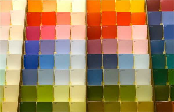
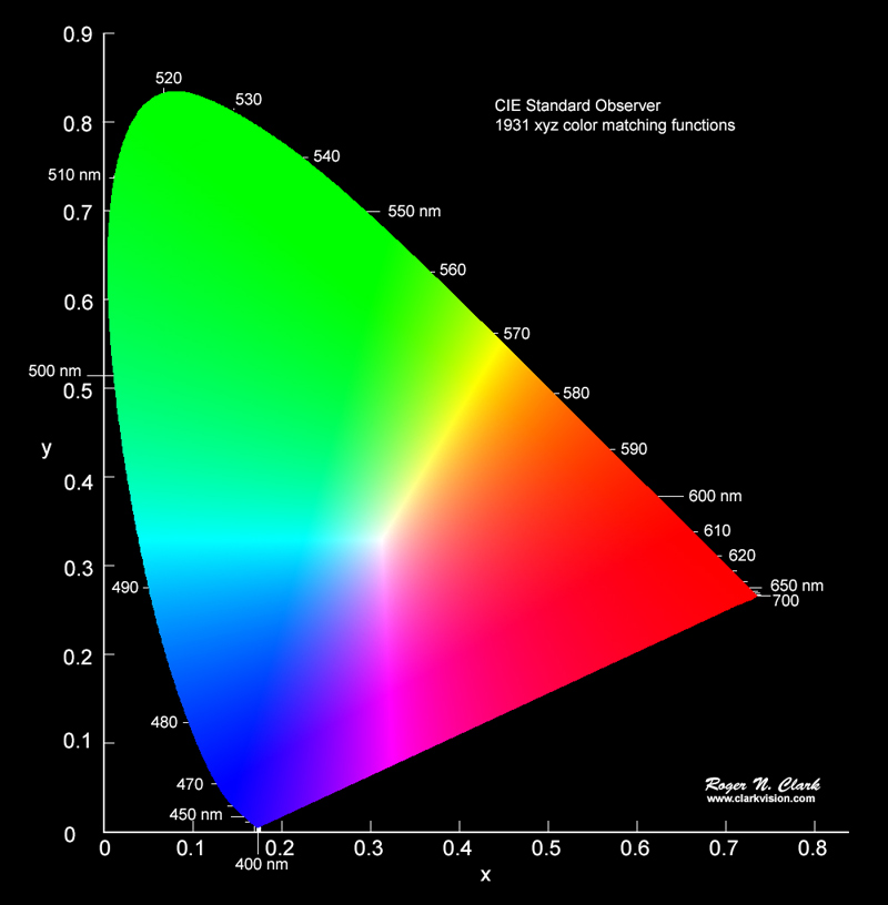
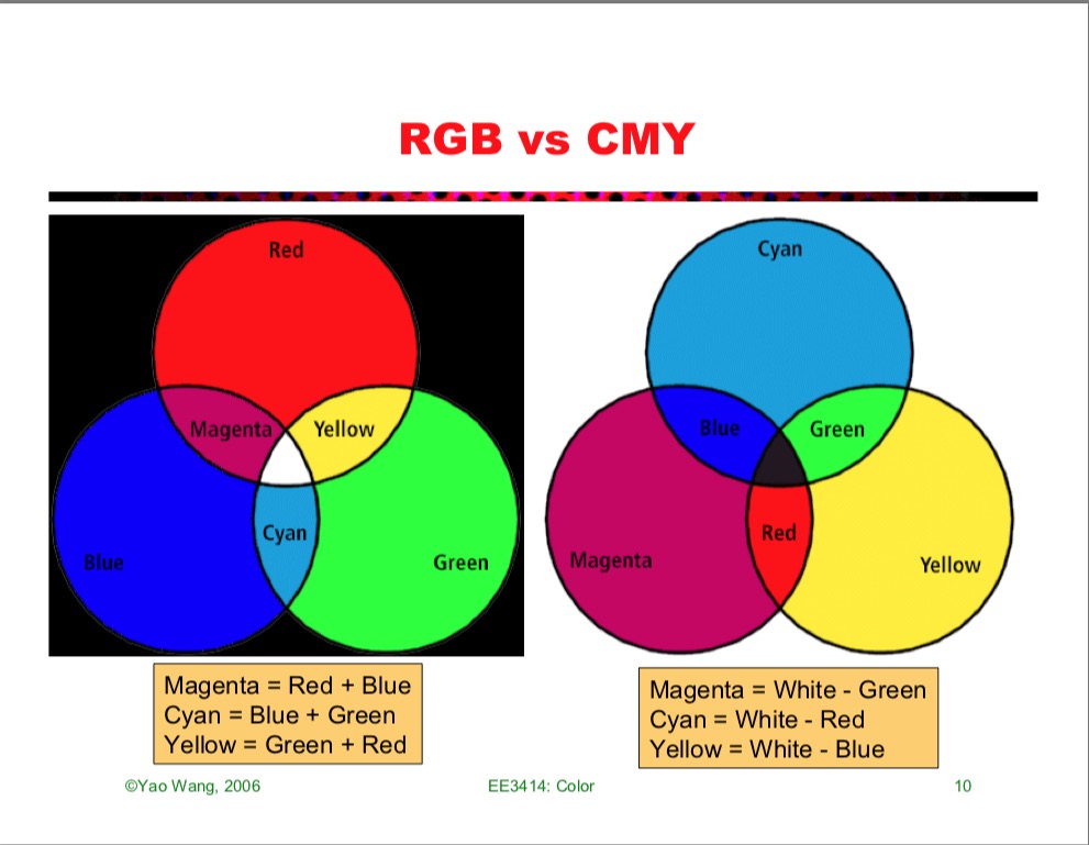


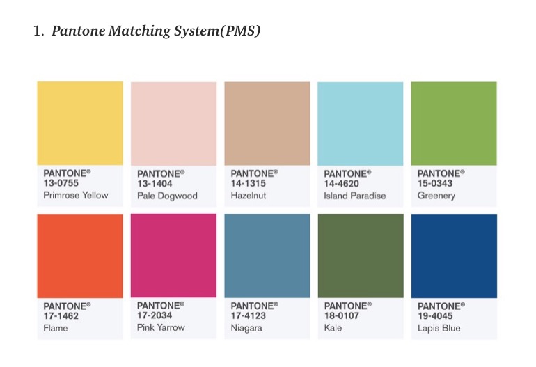

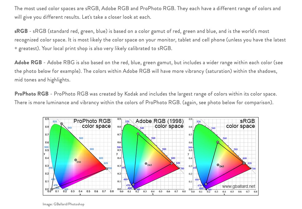
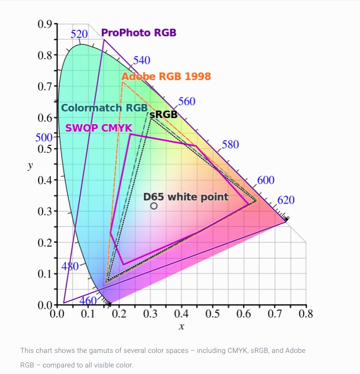
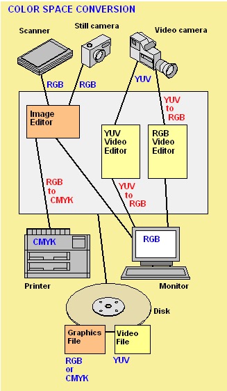
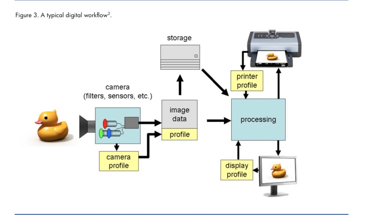
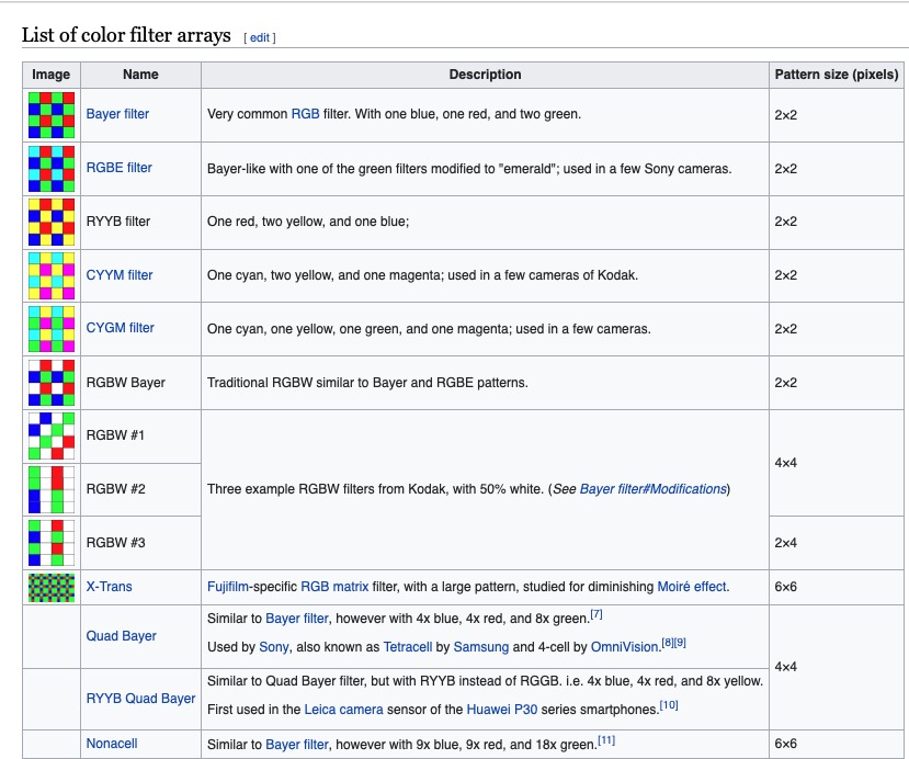
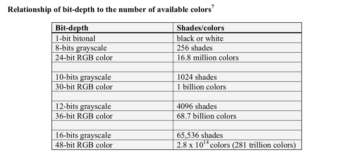

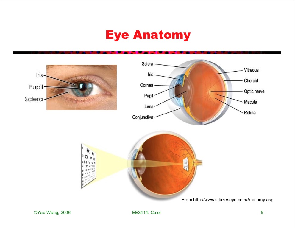
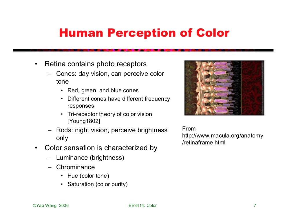
